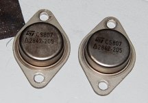
Haha! Very funny...
But Dave, these only have 2 legs. 😉
It just bugs me to no end when I can't find out what something is. Google and the internet have spoiled me.
But Dave, these only have 2 legs. 😉
It just bugs me to no end when I can't find out what something is. Google and the internet have spoiled me.
H
But Dave, these only have 2 legs. 😉
You'll find that the metal body is a vestigial 3rd leg 🙂
Maybe the cavalry can help...
dave
Have you measured it ? Does it read like a transistor or does it not 🙂
Have you connected it to a variable current limited PSU, say 15 ma max,0 to say 30 volts (all ways, all polarites) to see if it is a regulator.
Is it a triac or thyristor... again easy to check with the PSU.
Have you connected it to a variable current limited PSU, say 15 ma max,0 to say 30 volts (all ways, all polarites) to see if it is a regulator.
Is it a triac or thyristor... again easy to check with the PSU.
Looks like a typical TO-3 package (should have two pins on the bottom offset from center).
This is most likely just a power transistor. All TO-3 package devices use the body as the collector connection in the case of bipolar junction transistors. With MOSFETs it becomes the drain connection. There are other components available in this package but they're less common; you might find voltage regulators (like the K version of the popular LM317 voltage regulator), thyristors (SCR and TRIAC), etc.
If you were to look at it from the bottom with the pins offset to the left, the bottom pin would be base and the top pin emitter. Try attaching one lead of your DMM to the base and then the other to either emitter or collector (in diode-test mode). If it's PNP, you'll get readings with the negative lead to the base and if NPN, the opposite.
Have you measured it ?
No, I just pulled it yesterday and didn't have a chance to do anything, other than photograph it. I was hoping that someone would recognize the numbers.
Looks like a typical TO-3 package (should have two pins on the bottom offset from center).
This is most likely just a power transistor.
Looks like an NPN.
These are from a Lorain DC to DC converter (24VDC@12A to 50VDC@6A) and were mounted on a heatsink at the rear. In lieu of any other possible candidates, these must be the outputs.
Nice to have the specs for them though.
Power dissipation will be in the 150W to 250W range. Check Vbe (~0.6V is Silicon and ~0.3V is Germanium). If you see ~1.2Vbe and ~0.6Vbc or so then it's a darlington transistor.
Hfe is typically in the 15 to 70 range depending on what sort of transistor it is (unless it's a darlington). If it's an old-fashioned switching converter and the transistors are silicon then possibly an fT of 1MHz area?
Vceo is probably something between 70V and 120V given the application. It could be lower but that's not so common.
Ic will be in the 15A or more area if the converter is designed the way I think it is.
These are just ballpark figures and cannot be relied upon if you think you'll push the transistor's limits.
I would happily throw a pair of these into a quasi-complementary audio output stage delivering 60W without knowing anymore than my above guesses. Stability would be trial-and-error but really not at all difficult.
Last edited:
You might try contacting the maker of the gear they came from for schematic and tech data, and you might contact ST and see if they can shed any light on those house numbers.
I would happily throw a pair of these into a quasi-complementary audio output stage delivering 60W without knowing anymore than my above guesses. Stability would be trial-and-error but really not at all difficult.
Thanks!
My projected use for these is power supply related, though I haven't settled on anything firm yet.
I'll do a bit of testing on them this weekend if I have time.
You might try contacting the maker of the gear they came from for schematic and tech data, and you might contact ST and see if they can shed any light on those house numbers.
That is an idea but I'm not sure if it is worth the trouble.
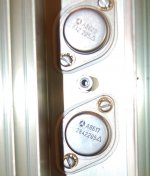
I have a total of 4 of these. The second set is from another identical unit, but the manufacturer is not ST:

That logo looks familiar but I can't place it. Notice the bottom numbers are the same as the others but the top sequence is different - possible production related numbers?
I used to work for a large multinational. Virtually every semconductor had special part numbers that were used just for us, nobody else. Once in a while I would get a board and it would have 2 sets of partnumbers on the chips etc. One was the oem number and the other was the regular 2nXXXX or SN7404 or whatever. So for a while I made my own cheat sheat with a conversion table. oem part number and normal number. Why do you ask did I do that? Well once in a rare while it would be 3 o'clock in the morning and I needed to fix a board to get the customer up and running. The early systems that I worked on had real schematics and it was possible to trouble shoot down to the part level. Once or twice in a rare while I was able to take 2 bad boads and make one good one and make a very unhappy customer happy. In later years it was more like if a fault code was displayed change one of the following 3 boards to fix the fault. If the fault still happens replace them again and pray to the CE gods. The second picture looks like a motorolla part number( On semi now), the 4 digits starting with 8 are probably the date codes.
The lower number is their part number, and the upper number is the date code.
An email to any involved party costs nothing, just a matter of how curious you are.
An email to any involved party costs nothing, just a matter of how curious you are.
An email to any involved party costs nothing, just a matter of how curious you are.
Already sent an email to ST here in Mississauga, Ontario yesterday. Awaiting reply.
Thanks!
That logo looks familiar but I can't place it. Notice the bottom numbers are the same as the others but the top sequence is different - possible production related numbers?
Semiconductor Logos is a good site to bookmark when trying to identify unknown devices.
- Status
- Not open for further replies.
- Home
- Design & Build
- Parts
- Anyone Know What These Are?
