Hi Krisfr,
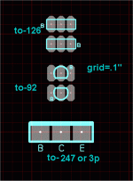
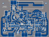
I don't know the layout program you are using but you might want to try to redraw the footprint of the TO-92's to spread the pads out a bit. This will give you more clearance for traces and be much easier to solder.
These are 1.5mm traces and 2.2mm pads:
View attachment 197610
Most to-92's I order (5 types - 100 at a time) are in "ammo paks" ...

2.5mm lead spacing - 5mm from b-e. They will fit the same pads as the to-126's (below #1 - all packages on 2.5mm - .1" grid). I'm not sure about Kicad and whether you can create your own component library , but I found both Kicad and sprint to have "dated" libraries that DO NOT reflect audio PCB design. Luckily , Sprint allowed me to create my own.
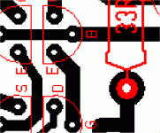
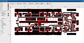
Krisfr , I noticed your Kicad output was aliasing (Pix 2) larger traces and/or a greater resolution would be preferable. Just as an example , (pix3) is a 200W OPS .. proven and DIY proof (can't lift pads - all lead spacing verified).
I suggest printing the output of the layout and physically placing parts on the paper so there will be no future surprises. 😱😱 Lay your board out for real parts , not what the CAD predicts.

OS
Attachments
Last edited:
I am at the front of a learning curve...
I have done too many DIGITAL boards with 7 mil traces between the DIP pads...
Thanks for all that are trying to teach me a thing or two...
I will be up to speed by the end of the week month or year....
Thanks🙂
I have done too many DIGITAL boards with 7 mil traces between the DIP pads...
Thanks for all that are trying to teach me a thing or two...
I will be up to speed by the end of the week month or year....
Thanks🙂
Last edited:
I would never make such a rash promise !....I will be up to speed by the end of the week month or year....
Did'nt realise my "zah-ng" amp was a bit similar in topology but complementary. well nothing new under the sun. So I can understand that it's probably good.
Hav'nt heard goldmund but yes, my amp sounds good, confirmed by a lot of people.
An interesting aspect of it is the spice simulation, it's possible to squeeze thd of theese topolgies down to like 9 decimals or something , but of course in reality it gets around 0.00xx something.
So I say dump output transistors and put irfp's there (and compensation) and make it fully complementary.
Last edited:
It's not complementary already...?
- keantoken
yeah yeah , I forgot the word "fully" ,marking words.. yes I know there is a lack of available components for that but then make it into a circlotron then or something..
Last edited:
Is there a schematic of your amp anywhere? I didn't find anything on google.
- keantoken
Maybe you should look at nikwal's signature...
 😀
😀Nah, of course not, why would it be there? lol
I was actually at this site a long time ago, and found myself admiring the circuits. Nice.
- keantoken
I was actually at this site a long time ago, and found myself admiring the circuits. Nice.
- keantoken
REST IN PEACE
THIS THREAD IS DYING A SLOW NATURAL DEATH, TOOK ONE MONTH TWO DAYS AND 990 POSTS. I GUESS NO "Mods, Improvements, Stability" ISSUES AND IT IS SAFE TO ASSUME THERE REALLY IS NOTHING IN THE WORLD THAT BEATS THE GOLDMUND
MAYBE WE CAN LISTEN TO THE SHUNT REGULATOR IN THE MEAN TIME, OR WILL THERE BE SOME SECRET REVELATION FORTHCOMING.
THIS THREAD IS DYING A SLOW NATURAL DEATH,
 TOOK ONE MONTH TWO DAYS AND 990 POSTS. I GUESS NO "Mods, Improvements, Stability" ISSUES AND IT IS SAFE TO ASSUME THERE REALLY IS NOTHING IN THE WORLD THAT BEATS THE GOLDMUND
MAYBE WE CAN LISTEN TO THE SHUNT REGULATOR IN THE MEAN TIME, OR WILL THERE BE SOME SECRET REVELATION FORTHCOMING.

Truth is that it cant be improved beyond hitachi s original implementations..
As can be seen, goldmund used a simplified version of hitachi s HMA 7500MK2..
All in all , goldmund s amp has nothing extraordinary.
Its linearity is poor, and the relatively high slew rate
is obtained at the expense of stability..
http://www.diyaudio.com/forums/solid-state/162763-hitach-lateral-mosfets-back-march-1978-a.html
Obviously I can't do everything. If I'm the only one moving this thread forward, of course it's going to die. If someone builds it and tests it and shows anything more than armchair interest, I'll start working on the PCB layout again. For however much interest this thread seems to have gained, only a few people have been participating.
And I do have things to do other than "herd the cattle" as some people have chosen to put it. If the cattle want to be somewhere else, it is a waste of my time - I buy my beef from the grocery store.
- keantoken
And I do have things to do other than "herd the cattle" as some people have chosen to put it. If the cattle want to be somewhere else, it is a waste of my time - I buy my beef from the grocery store.
- keantoken
Well , i made numerous sims of this kind of amp topology, including
the goldmunds.
Although it can t compete with more refined topologies, at least in my tries,
it can be greatly improved, particularly on the THD front.
Edit : some numbers
the goldmunds.
Although it can t compete with more refined topologies, at least in my tries,
it can be greatly improved, particularly on the THD front.
Edit : some numbers
Attachments
Last edited:
Hi,
pretty nice Japanese style design, I would reduce the rail voltages for the output FETs below 50V, lower the open-loop gain, and omit the protection diodes to begin with. The bipolar transistors (in post #1) have poor sound quality.
pretty nice Japanese style design, I would reduce the rail voltages for the output FETs below 50V, lower the open-loop gain, and omit the protection diodes to begin with. The bipolar transistors (in post #1) have poor sound quality.
Obviously I can't do everything. If I'm the only one moving this thread forward, of course it's going to die. If someone builds it and tests it and shows anything more than armchair interest, I'll start working on the PCB layout again. For however much interest this thread seems to have gained, only a few people have been participating.
And I do have things to do other than "herd the cattle" as some people have chosen to put it. If the cattle want to be somewhere else, it is a waste of my time - I buy my beef from the grocery store.
- keantoken
I have been waiting for you to complete the shunt, when EVER you do I will layout a pcb and build and test... The pcb might not be perfect, BUT it will be made and tested...😀
IMHO the thread needs to move toward building and testing IF it is to keep interest up and survive...otherwise it will be discussed to death.
I have more than armchair interest 😉
Thanks
Last edited:
OK, what is the stauts of this thread?
Are the shunt regulators done? If not, what issues remain open? If so, what post contains the schematic?
What about the amp? Front end? Power section? Issues? Schematics?
Are the potential issues listed in post 1 still open? (I think it was post 1.)
Are the shunt regulators done? If not, what issues remain open? If so, what post contains the schematic?
What about the amp? Front end? Power section? Issues? Schematics?
Are the potential issues listed in post 1 still open? (I think it was post 1.)
Assuming the SHUNT regulator is done, will we be using the regular regulator that OS designed to feed it?
And IF it is done and the regular regulator is needed, then are we ready to get a designed and approved then built and tested pcb?
And IF it is done and the regular regulator is needed, then are we ready to get a designed and approved then built and tested pcb?
I dropped out as KT is obliviously mad at me or something. I am a dolt , but at least I will have a completed Lateral (pix1) + Fet goldmund (pix2) done by 12/5/10. WAY too much time on the regulator , that could be done afterwards with the amplifier set up to take a secondary set of rails.
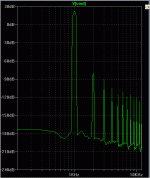
Wahib , yes.. this topology will do MUCH better (pix 3 - FFT of pix 2). Carlo's little "blame ES" voltage stage sounds better than any of Nagsy's clones with a , it is the output stage that gives the goldmund the "magic". I would not call them "cattle" , but the "cover" is more important than the content... people are frivolous indeed to commit to a mere subjective opinion. "BEST amp in the world" HA HA LOL... 🙄 My ar_se.
I was reading the "blowtorch" threads and all the pass material and it took YEARS for any viable projects to come of these.Some threads just "yap" and produce nothing. APEX , DX , MJL , and myself are the only ones who actually build and share anything. So 1 month is not a fair timeline to judge.
OS
Attachments
- Home
- Amplifiers
- Solid State
- Goldmund Mods, Improvements, Stability
