Hi, tube folks !
Having run into strange problems I'm now have to call for community help.
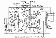
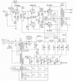
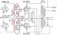
I have built 40W PP AB1-class 6L6GC amp 485V B+ 5K, original Sansui AU-111 schematic and mod (made by someone in Japan) both attached. The guy from Japan built a power amp using original AU-111 transformers. I stayed upon original schematic (I kept RC 150pF + 22K in cathode of 6AQ8 which seem to help improve stability).
Since I did not have original Sansui AU-111 transformers, I used my own 60W unit, which also have 5K primary, separate CFB (same as original), and linear frequency response from 20Hz - 100 KHz. Amp is being powered by stabilized regulated power supply capable of 360 - 500V 0.5A. For a while I used 6P3S-E (40 mA idle current) instead of 6L6GC (I have Shuguang 6L6GC, but they seem to be behaving unstable under 485V B+, cannot keep idle current constant).
First check I did with oscilloscope and generator. Amp is capable of 16 - 17V RMS output voltage (which corresponds to 36 - 40W of output power) on 8 Ohm load (50W resistor), very nice smooth looking sinewave. Square-wave also seem to be good even on 10 KHz frequency. Unfortunately, I have single-beam oscilloscope and cannot compare two sinewaves side by side and guess THD.
Now the most strange. Measuring frequency response with ARTA (and RMAA), I found that amp has a 6dB peak at 20 KHz, smoothly rolling off till 50 Hz. The rest of frequency response curve is OK. I removed 0.3 uF cap from NFB loop (C66 on original schematic). Peak have gone, but now frequency response curve is like a +/-2dB zigzag in range of 20 - 50 Hz.
Measuring THD/IMD yielded even more strange results. I used 2 software packages - RMAA and Arta, ESI Juli sound card, and big wirewound 10 Ohm pot as load and voltage divider (in order to protect sound card input).
RMAA showed clipping even at 5V RMS output from amp (about 0.5V on sound card input). With low signal level, RMAA THD measured at 1.5%, and IMD at 4.5%. It is clearly out of factory specification, it should be <0.8% and 1% respectively. Something way wrong. For whatever reason (I'm not understand why), ARTA never showed THD value (may be something wrong with my options setup ???), and IMD 4.5% at low level, 28% at 16V RMS (horribly high).
The first thing come into mind is to replace tubes what I of course did (I have tube tester so I can check them, all were OK). Second, it could be wrong polarity of CFB winding, but in this case it is not (amp oscillates if CFB connection polarity is wrong).
Thanks in advance for any suggestion or help.
Having run into strange problems I'm now have to call for community help.
I have built 40W PP AB1-class 6L6GC amp 485V B+ 5K, original Sansui AU-111 schematic and mod (made by someone in Japan) both attached. The guy from Japan built a power amp using original AU-111 transformers. I stayed upon original schematic (I kept RC 150pF + 22K in cathode of 6AQ8 which seem to help improve stability).
Since I did not have original Sansui AU-111 transformers, I used my own 60W unit, which also have 5K primary, separate CFB (same as original), and linear frequency response from 20Hz - 100 KHz. Amp is being powered by stabilized regulated power supply capable of 360 - 500V 0.5A. For a while I used 6P3S-E (40 mA idle current) instead of 6L6GC (I have Shuguang 6L6GC, but they seem to be behaving unstable under 485V B+, cannot keep idle current constant).
First check I did with oscilloscope and generator. Amp is capable of 16 - 17V RMS output voltage (which corresponds to 36 - 40W of output power) on 8 Ohm load (50W resistor), very nice smooth looking sinewave. Square-wave also seem to be good even on 10 KHz frequency. Unfortunately, I have single-beam oscilloscope and cannot compare two sinewaves side by side and guess THD.
Now the most strange. Measuring frequency response with ARTA (and RMAA), I found that amp has a 6dB peak at 20 KHz, smoothly rolling off till 50 Hz. The rest of frequency response curve is OK. I removed 0.3 uF cap from NFB loop (C66 on original schematic). Peak have gone, but now frequency response curve is like a +/-2dB zigzag in range of 20 - 50 Hz.
Measuring THD/IMD yielded even more strange results. I used 2 software packages - RMAA and Arta, ESI Juli sound card, and big wirewound 10 Ohm pot as load and voltage divider (in order to protect sound card input).
RMAA showed clipping even at 5V RMS output from amp (about 0.5V on sound card input). With low signal level, RMAA THD measured at 1.5%, and IMD at 4.5%. It is clearly out of factory specification, it should be <0.8% and 1% respectively. Something way wrong. For whatever reason (I'm not understand why), ARTA never showed THD value (may be something wrong with my options setup ???), and IMD 4.5% at low level, 28% at 16V RMS (horribly high).
The first thing come into mind is to replace tubes what I of course did (I have tube tester so I can check them, all were OK). Second, it could be wrong polarity of CFB winding, but in this case it is not (amp oscillates if CFB connection polarity is wrong).
Thanks in advance for any suggestion or help.
Attachments
Only thought I have at the moment is to go back and check that the cathode feedback windings to the output stage cathodes are not swapped. This caused similar problems in some designs of mine where I initially got them backwards.
Last edited:
Is the amp stable with C66 removed? Is output bias correct? High distortion probably means either wrong bias or oscillation.
The 150pF+22K may need adjusting to suit the transformer
The 150pF+22K may need adjusting to suit the transformer
Thanks for everyone who replied !
Output tubes are biased at 40 mA each. I disconnected CFB (amp will work without it anyway) and did measurements again. Low-frequency peaks/dips went down to +/-1.5dB, but high THD/IMD are the same abnormally high (8 - 10% IMD at 10V RMS / 10 Ohm load) - something way wrong. Schematic is OK for sure since it is Sansui AU-111.
Removing C66 did not affected stability at all, I see no oscillation on oscilloscope. However, amplification factor of amp went up from 10 to 28 (or am I have hallucinations ???).
I connected input & output of sound card with straight cable (in order to verify if card/software is malfunctioning), everything is OK.
One note. NFB loop in Sansui AU-111 was connected to 16 Ohm tap of output transformer. Since main have only 4/8 Ohm taps, I connected it to 8 Ohm tap.
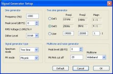
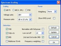
I attaching ARTA settings, anyone can suggest why it is not showing THD? Or this is just a software glitch?
Output tubes are biased at 40 mA each. I disconnected CFB (amp will work without it anyway) and did measurements again. Low-frequency peaks/dips went down to +/-1.5dB, but high THD/IMD are the same abnormally high (8 - 10% IMD at 10V RMS / 10 Ohm load) - something way wrong. Schematic is OK for sure since it is Sansui AU-111.
Removing C66 did not affected stability at all, I see no oscillation on oscilloscope. However, amplification factor of amp went up from 10 to 28 (or am I have hallucinations ???).
I connected input & output of sound card with straight cable (in order to verify if card/software is malfunctioning), everything is OK.
One note. NFB loop in Sansui AU-111 was connected to 16 Ohm tap of output transformer. Since main have only 4/8 Ohm taps, I connected it to 8 Ohm tap.
I attaching ARTA settings, anyone can suggest why it is not showing THD? Or this is just a software glitch?
Attachments
Look closely at the region around the zero crossing of the output signal. Does it appear to have a higher or lower slope than the region a bit further away from zero? A clean sine wave will show a smooth increase in slope towards zero. Any sudden increase or any decrease means crossover distortion. Sudden increase means output quiescent current is too high. Decrease means output current too low.
Removing C66 will increase HF gain, but mainly above the audio region.
Moving the NFB tap from 16 to 8ohms would involve a reduction in feedback resistor to maintain the same conditions. Better to leave it on 16 ohms tap. However, even on 8ohms tap it won't do much harm, just increase gain and distortion a little.
Output oscillation may be RF and won't make it through the OPT, so not seeing it at the output does not guarantee that it isn't happening. You could try increasing the output grid stoppers, or adding g2 stoppers.
Test on Oscilloscope
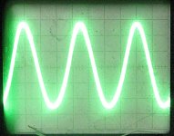
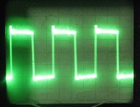
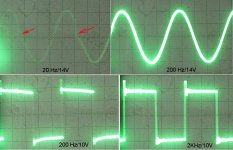
I took a data from oscilloscope, 10V RMS output:
1) 20 Hz sinewave, visibly distorted;
2) 2 KHz, square wave (small overshoot, undershoot and ringing are normal);
3) 20 KHz sinewave, visible asymmetry, or just my imagination ?
Any comments/interpretation?
I took a data from oscilloscope, 10V RMS output:
1) 20 Hz sinewave, visibly distorted;
2) 2 KHz, square wave (small overshoot, undershoot and ringing are normal);
3) 20 KHz sinewave, visible asymmetry, or just my imagination ?
Any comments/interpretation?
Attachments
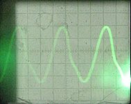
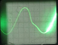
Nothing obvious. Low frequencies often look a bit distorted, as capacitor charges shift around a bit during the cycle. The 20kHz doesn't look quite right; there is some asymmetry.
Last edited:
Update: I made small progress in debugging the amplifier. As I told before once I have overheated the tube, and once even occasionally shorted two wires while measuring voltage (fuse was blown and PCB developed some burn marks).
I have cleaned PCB and replaced one of the 10 ohm cathode protection resistors which was seem to be measuring fine but looked strange due to the physically close location to recent short.
Additionally, I have increased idle current of 6L6GC output tubes from 40mA to 50mA (with 485V B+ voltage).
At relatively small signal level (several V) THD went down to 0.8% which is what it supposed to be. Unfortunately, once output level increases distortions also go unacceptably high. They are clearly visible on oscilloscope. What is really strange, 200 HZ/14V sine-wave looks perfectly fine, while 20 Hz is visible distorted crossing zero region (switching tubes ?).
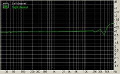
Frequency response is +0.1/-0.12dB in 20Hz - 20 KHz range (look at the image attached), noise level -94dB.
+1dB/-0.5dB peaks/dips above 30 KHz do not matter, not audible anyway.
Suspecting power supply problem, I did the following. I disconnected amp from 6080-based regulated voltage stabilizer, and connected straight to the CLC filter (200 uF + 5H + 50uF). Then, I even removed 5H choke. Nothing changes.
Output transformer was another possible culprit - or to be precise, saturation of core at low frequencies. Reducing idle current of one of output tubes down from 50mA to 40mA, I got the following results at 20Hz:
Idle current VL1/VL2 --- V(out) --- W(out) --- Drop (dB)
I1=I2=50 mA --- 15V --- 28.13W --- (0dB)
I1=50 mA, I2 = 40mA --- 14V --- 24.5W --- (-0.6dB)
I1=50 mA, I2 = 33mA --- 13V --- 21.13W --- (-1.24dB)
Although distortions went visibly higher, output level dropped insignificantly, only -1.24dB. And this with imbalance which is simply huge by any means ! Thus, transformer core is very far from saturation.
Any comments or ideas what still could be wrong?
I have cleaned PCB and replaced one of the 10 ohm cathode protection resistors which was seem to be measuring fine but looked strange due to the physically close location to recent short.
Additionally, I have increased idle current of 6L6GC output tubes from 40mA to 50mA (with 485V B+ voltage).
At relatively small signal level (several V) THD went down to 0.8% which is what it supposed to be. Unfortunately, once output level increases distortions also go unacceptably high. They are clearly visible on oscilloscope. What is really strange, 200 HZ/14V sine-wave looks perfectly fine, while 20 Hz is visible distorted crossing zero region (switching tubes ?).
Frequency response is +0.1/-0.12dB in 20Hz - 20 KHz range (look at the image attached), noise level -94dB.
+1dB/-0.5dB peaks/dips above 30 KHz do not matter, not audible anyway.
Suspecting power supply problem, I did the following. I disconnected amp from 6080-based regulated voltage stabilizer, and connected straight to the CLC filter (200 uF + 5H + 50uF). Then, I even removed 5H choke. Nothing changes.
Output transformer was another possible culprit - or to be precise, saturation of core at low frequencies. Reducing idle current of one of output tubes down from 50mA to 40mA, I got the following results at 20Hz:
Idle current VL1/VL2 --- V(out) --- W(out) --- Drop (dB)
I1=I2=50 mA --- 15V --- 28.13W --- (0dB)
I1=50 mA, I2 = 40mA --- 14V --- 24.5W --- (-0.6dB)
I1=50 mA, I2 = 33mA --- 13V --- 21.13W --- (-1.24dB)
Although distortions went visibly higher, output level dropped insignificantly, only -1.24dB. And this with imbalance which is simply huge by any means ! Thus, transformer core is very far from saturation.
Any comments or ideas what still could be wrong?
Attachments
Last edited:
It looks like one valve is cutting off before the other gets going. Could be low bias, or a bias shift due to the low frequency. Maybe some other imbalance which only happens at lower frequencies. I have seen this sort of thing with cathode bias, but you have fixed bias.
I took signal from the both triodes of the inverter 12BH7A. Looks OK, no distortions.
Take a look at the 12BH7A output with the secondary output voltage at 10Vrms, and the feedback disconnected - let's make sure your driver is not running out of steam. Repeat with the output tubes removed if there is any question.
Check the screen supply, and make sure the secondaries are all correctly configured.
If all of the above is exonerated the problem almost has to be bad OPTs or output tubes.
Last edited:
Also, what is the wattage rating of your load resistor?
50W, its hot but not smoking.
50W, its hot but not smoking.
At least double of the output rating is recommended. The load resistor changes its' value while heating, thus may give inaccurate results. Output stages often change their characteristics with different loads.
It looks like one valve is cutting off before the other gets going. Could be low bias, or a bias shift due to the low frequency.
Many thanks, FD86 !
BIAS is fixed to optimal tube operation at 485V B+ voltage - 40 mA for 6P3S-E and 50mA for 6L6GC. BTW, how to determine and fix BIAS shift you mentioned in your reply?
I slightly modified BIAS supply, I have installed 500uF + 0.1 uF caps after rectifier, and omitted 4x47uF V caps installed just after BIAS potentiometers. Original amp have very long BIAS supply wires, and most probably these caps were needed to suppress hum.
Take a look at the 12BH7A output with the secondary output voltage at 10Vrms, and the feedback disconnected - let's make sure your driver is not running out of steam. Repeat with the output tubes removed if there is any question.
Actually I use 6N6P instead of 12BH7A, they are very close to each other. I did check of inverter at low signal level with output tubes removed, now have to repeat with 1.5V input.
I have second transformer from the same pair, no changes whatsoever of amp behavior after replacement.
Really weird.
Many thanks, FD86 !
BIAS is fixed to optimal tube operation at 485V B+ voltage - 40 mA for 6P3S-E and 50mA for 6L6GC. BTW, how to determine and fix BIAS shift you mentioned in your reply?
I slightly modified BIAS supply, I have installed 500uF + 0.1 uF caps after rectifier, and omitted 4x47uF V caps installed just after BIAS potentiometers. Original amp have very long BIAS supply wires, and most probably these caps were needed to suppress hum.
If the same amount of fixed bias is supplied to both tubes in PP, variations of parameters between the two tubes may cause non-symmetric output signal and distortion.
Also, I would restore the caps to the bias potentiometer, though this isn't the cause of your present troubles (probably).
Don't forget that you will always get some LF distortion due to the OPT. At 20Hz the inductive reactance will be low enough that transformer action will be reducing. This means that the voltage waveform at the anode, cathode and output may be slightly different. This in turn means that the cathode feedback is not pure negative feedback but may actually introduce distortion of its own. Look at 50Hz too. The power bandwidth of a valve amp will always be smaller than the small-signal bandwidth.

- Status
- Not open for further replies.
- Home
- Amplifiers
- Tubes / Valves
- Please Help - LF Peaks/Dips & Clipping