Life sucks, and i'll be washed up in 4 hours from now
Awe...nothing to fret. My heart beats with the eb and flow of the Eastern Atlantic tides and I was born on a ship locked in ice. Way off topic...I'll retire my antics and let the thread resume its HiFi potential.
I tip my hat to this thread. There is no emoticon for tipping the hat. Can some web guru add that? I'd really like that.
Thanks a mint chaps.
by Keentoken - Stability is traded for HF impedance.
I seem to have the same issue , my stability is being traded for HF PPM(TMC). BTW, it is not a "dead fish oscillator" , it really works in real life.
 Perfection is a trade off ... how low imp. do you really need at 10K??, and do I need 20ppm -THD20?? (I sure each of us can come real close). It all equates to what beneficial sound/performance aspect will each refinement actually produce AND at what cost to stability/Reliability. 🙂
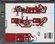
 Krisfr , below is a partitioned (zoned) layout just a couple traces away from keen's design. Since you seem to like a modular approach , look at the attachment below for inspiration. All "rules of engagement" are in place. 😀 Just an example , fatter pads , a few jumpers are better than long traces or traces that conflict (NFB-anything / input-output).
OS
Attachments

MIIB, this can work, and the total output impedance will be the parallel impedance of the shunt and series reg. Actually in this case, the shunt would usually be something like a JLH ripple-eater (AKA shunt C-multiplier). The trouble is that you then have 2 regs together which both have different phase characteristics, so it may be difficult to get stable unless you start from the load and work back, rather than trying to design it for many different loads.
Mosfet, it seems you are right, and I hope the trend catches on. Wouldn't it be ironic if the amp turned out to sound awful? Speaking of keeping the iron hot, I've left it on overnight accidentally quite a few times. It helps in the winter months.
OS, AFAIK, the rise in THD with HF relates with TIMD/whatever. Take a NGFB circuit for example. No TIMD, just a multi-transfer curve, and minimal time-related distortions. Then consider NFB amps. Often times, OLG does not fill the audio band and so there is a THD/error rise in the treble. My experience with my headamp indicates that global THD is not so important, but it is the rise in THD with frequency that causes harshness. Oddly enough, this amp has 100Hz OL BW, which goes against this analysis, but this is easily changed by increasing the Jfet degeneration, which should be included as an option.
OS, I've been thinking perhaps we should have power planes as well. Say the ground plane is on bottom, and the top contains the component traces except the empty space is connected to the rails. If we could sort out a power plane type board, then the frontend would have better regulation, with minimal trace inductance. Plus the rail parasitic capacitances would couple to the ground plane.
I am changing the bottom 2 Wilson transistors to KSC1845's, since these don't dissipate much of anything. They should be coupled face-face though. OS, I see you lost the 4th transistor of the Wilson. Simulation agrees with this but simulation has rather poor Hfe-Vce modeling. Anyone worried about the cash can jumper it I guess.
My first experimental iteration of the PCB... The TO126's mount on top of one another, and to the PCB in pairs. Think this is good enough heatsinking? The bottom one will be clamped to the negative rail copper. I want to do this with the drivers as well. Notice the split planes at the upper left rail, with the decoupler next to the bridge.
- keantoken
Attachments
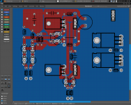
The evolution... R15 being a 1k resistor won't last 7W dissipation, and it would be bulky to put on the board, so I will use a 1W 10k resistor instead. Notice the copper plane underneath - theoretically this will drain any interference from nearby traces. Also note the super special quantum guard trace around the NFB trace. Way cool.
Discussion? Complaints? What packages would I see used for the Jfets besides TO92?
PS, I'm probably using the software totally wrong, in fact I'm sure of it.
- keantoken
Discussion? Complaints? What packages would I see used for the Jfets besides TO92?
PS, I'm probably using the software totally wrong, in fact I'm sure of it.
- keantoken
Attachments

and introduce additional parasitic capacitances between components and/or traces.Notice the copper plane underneath - theoretically this will drain any interference from nearby traces.
Yes, all .2pF of it worst case (by rough estimate). Plus it's shorted to ground.
Parallel Plate Capacitor Capacitance Calculator
- keantoken
Parallel Plate Capacitor Capacitance Calculator
- keantoken
Last edited:
(other than that, i used to beat up folks at night, for cash, so nothing)
Jacco, I don't know if I should embrace you or punch yer feckin lights out? I bet a KSA100+ amp that I could put you to shame...physically. My pincer and crusher's would get you done in no time. AND i'd get that bilge pump of yers dry in no time! 🙂
Meet you in the dry docks,
SJH.
Should the SHUNT regulators be on the same board as the input/VAS?
Should the DC voltage supplying the SHUNTS be on separate board with the transformers and ac controls?
Will there be ANY large electrolytic after the shunts have done their jobs? I think that defeats their(the SHUNTS) purpose...
A simple diagram would put all on the right page and forestall any future disagreements about parts placement and or positions.
Thanks to all, this is fun to say the least, at least for me.
And no Shanghaiing on the poop deck or youse all go to steerage.
OS, I am amazed, and I should not be at the true simularity to our respective layouts. Great minds run together...
NOW, if we can integrate Kean's SHUNT in, zone the Star ground system I think we are past the 50/50 point and well on our way to some scope time.
Yeah TEAM...
THanks
NOW, if we can integrate Kean's SHUNT in, zone the Star ground system I think we are past the 50/50 point and well on our way to some scope time.
Yeah TEAM...
THanks
I dont know much about regulators.....but to me in my mind it makes sense to have a fairly slow series regulator followed by a speedy shunt placed close to the audio circuits...the series regulator providing an over voltage and the shunt taking it down to the desired lower ripple free value...
or am I missing the point...??
Point well taken... and right on. HIGH integration of the Shunt into the front end VAS and Drivers, leave room for more than one topology... TOO.
The point with my comment was exactly that...I mean what's the point at a ultra low Z supply...if it's placed separately.. and we then add and increase the resistance in terms of wires and soldering......oh by the way what's the point of low z power supply when all that's connected to it is resistors and current sources..??
Target must be low low noise.....and elimination off any diode recovery HF..crap.
Target must be low low noise.....and elimination off any diode recovery HF..crap.
I have always found that shunts work best when they are placed right next to the circuit they are powering this also holds true for other regulators, AC on the other hand should be placed as far away from the input as possible, just my two cents.
Jam
Jam

placed right next to
On both sides of the circuit.
With shunt + series, the shunt at the AC side, series regs smack right at the entrance.
Think BT and a few others, whatayaknow, i just saw one other.
(that's it, you can hit me now, SJH. 41hrs no sheep, just 0.5hrs in the bath tub.)
Last edited:
(that's it, you can hit me now, SJH. 41hrs no sheep, just 0.5hrs in the bath tub.)
Just kidding. I'm a whimp.🙂
Last edited:
41hrs no sheep, just 0.5hrs in the bath tub.
Baaaaaaaa-aaaaaa
Attachments

A question about shunts. Do shunts ALWAYS sound better than series regs, or it is that most series regs are designed inferior? I ask this because my series reg design has better specs all around.
BTW, our shunt has 68 ohms DC impedance, so maybe we could reasonably hang it off a series reg with some impunity. Especially if the series reg has the same tempco, as would be the case with the schematics I posted earlier.
- keantoken
BTW, our shunt has 68 ohms DC impedance, so maybe we could reasonably hang it off a series reg with some impunity. Especially if the series reg has the same tempco, as would be the case with the schematics I posted earlier.
- keantoken
Actually, using the shunt with the series reg doesn't change much since the series reg already has better specs. Furthermore, resonance between both regs may be an issue unless I dumb down one of them, in which case it just seems like a big waste of money.
May be worth it if using a chip reg though.
- keantoken
May be worth it if using a chip reg though.
- keantoken
- Home
- Amplifiers
- Solid State
- Goldmund Mods, Improvements, Stability