you can't use two positive-side regulators to post-regulate your +/- 35 V supplies. There is no way to connect them so that the ground of the +/- 15 V will be common with the +/- 35 V supplies. Go ahead and think about that... you will find it is impossible. You can still use two positive side regs for the +/- 35 V supplies, but you will need to post-regulate using one positive and one negative (e.g. LM337). Same goes for -12 V, if you need that. You'll need to use a 7912.
The way I looked at it he wanted two positive supplies from one higher positive supply.
What has changed?
What has changed?
you can't use two positive-side regulators to post-regulate your +/- 35 V supplies. There is no way to connect them so that the ground of the +/- 15 V will be common with the +/- 35 V supplies. Go ahead and think about that... you will find it is impossible. You can still use two positive side regs for the +/- 35 V supplies, but you will need to post-regulate using one positive and one negative (e.g. LM337). Same goes for -12 V, if you need that. You'll need to use a 7912.
I would agree if TS needed + and - 15V, but as far as I know, he only needs +15 V (and +12 V).
you can't use two positive-side regulators to post-regulate your +/- 35 V supplies. There is no way to connect them so that the ground of the +/- 15 V will be common with the +/- 35 V supplies. Go ahead and think about that... you will find it is impossible. You can still use two positive side regs for the +/- 35 V supplies, but you will need to post-regulate using one positive and one negative (e.g. LM337). Same goes for -12 V, if you need that. You'll need to use a 7912.
Foolish me! You're correct.
The way I looked at it he wanted two positive supplies from one higher positive supply.
What has changed?
OP:
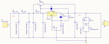
That could be ambiguous.Drops +/-35V from the main regulated power supply (sill in development, nearly there) down to +/-15V and +/-12V. Two of these in series will be used rather than using symmetric regulators (easier to construct this way, for one thing).
No problem. It's simple to change to a symmetrical supply. I don't expect additional caveats or pitfalls.
OK, symmetric design.
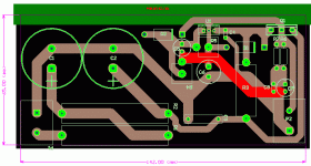
Return to zener pre-regulator stage to minimise complexity and PCB space + random (TM) aesthetic whim. Added fuses - rating is somewhat arbitrary given uncertain load of circuit and ~200mA is probably closer to being useful.
Return to zener pre-regulator stage to minimise complexity and PCB space + random (TM) aesthetic whim. Added fuses - rating is somewhat arbitrary given uncertain load of circuit and ~200mA is probably closer to being useful.
Attachments
Last edited:
OK, symmetric design.
Return to zener pre-regulator stage to minimise complexity and PCB space + random (TM) aesthetic whim. Added fuses - rating is somewhat arbitrary given uncertain load of circuit and ~200mA is probably closer to being useful.
OK, my bad, you did need symmetrical supplies.
Design looks OK to me, but I don't understand the -12V circuit if you're only going to need to switch some relays. You might as well leave it out and save yourself some space.
EDIT: is it on purpose that R2 and R3 are different values?
Last edited:
OK, my bad, you did need symmetrical supplies.
Design looks OK to me, but I don't understand the -12V circuit if you're only going to need to switch some relays. You might as well leave it out and save yourself some space.
EDIT: is it on purpose that R2 and R3 are different values?
Yeah, I'm thinking that dropping 12V is a good idea.
No, R3 is wrong. Well spotted.


I give up.
28posts to discover that Random does not know what he needs.
Hah. Sorry. I always said the 12V supply wasn't really needed (see OP). The +/-15V supply is and will power the buffer. I'm fairly sure it's all good now and will get on with constructing and testing.
Thanks for your copious help, Andrew.
Hah. Sorry. I always said the 12V supply wasn't really needed (see OP). The +/-15V supply is and will power the buffer. I'm fairly sure it's all good now and will get on with constructing and testing.
Thanks for your copious help, Andrew.
And I meant leave the -12 V-circuit out but the +12 V-circuit in...
You're absolutely right, I don't need the -12V in any circumstance. If I end up needing a +12 supply, it's simple to add a three component module to do the job.And I meant leave the -12 V-circuit out but the +12 V-circuit in...
This is looking good now. Thanks so much for your help.
- Status
- Not open for further replies.
- Home
- Amplifiers
- Power Supplies
- Simple DIY buffer PSU


