Helo,
I could use a hand from someone who has a few minutes and PSUD2 on their PC. My PC is down and al I have access to is a MAC for the next couple of days. I tried to run the PSUD2 program on the MAC but of course it won't work.
For who ever is up to the task here is the sim parameters
Tube full wave rectification with 6X4, 412VCT (206v per leg), CLCRC into a 20mA drain.
The CLCRC is as follows
C1= 95uF
L1= 30H at 915DCR
C2=50uF
R=1.5R
C3=100uF
Current drain at 15 to 40mA with a mean idle at 20mA
I don't have the transformer Output R so just use the default, it is not that important at this point.
I am interested in the final voltage at I1 (current drain) and the ripple voltage. Also want to know what the final I1 and ripple is with a 100R in place of the 1.5R.
If anyone wants to tackle this real quick I would very very grateful.
Thanks for your interest!
Jeff
Dude! What you need is VMware or Parallels. Then you can run both Windoze and Mac software on your Mac.
You could also set up MacSpice or something and just run a circuit simulation.
You could also set up MacSpice or something and just run a circuit simulation.
6X4 Cap input filter
Uh, Jeff, Dude (as Tom put it) you don't need simulation, you need an RCA Receiving Tube Manual. Please go go to Pete Millet's web site and download anyone from RC-20 to RC-30. These will have the 6X4 (and it's octal twin, the 6X5) in it. To save you some suspense, I'll mention that RCA recommended the first cap. after the rectifier to be 10 uF. With 95 uF right after the rectifier, I would expect the poor 6X4 to have a sparky, short, unhappy life. 😀 I hope this helps and I'm not trying to put you down or anything; just save a 6X4 from a fiery (tubelab kinda) death.
Uh, Jeff, Dude (as Tom put it) you don't need simulation, you need an RCA Receiving Tube Manual. Please go go to Pete Millet's web site and download anyone from RC-20 to RC-30. These will have the 6X4 (and it's octal twin, the 6X5) in it. To save you some suspense, I'll mention that RCA recommended the first cap. after the rectifier to be 10 uF. With 95 uF right after the rectifier, I would expect the poor 6X4 to have a sparky, short, unhappy life. 😀 I hope this helps and I'm not trying to put you down or anything; just save a 6X4 from a fiery (tubelab kinda) death.
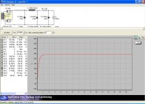
Here is with wa4htz mentioned 10uF max input cap. Note that there were warnings on both sims for overcurrent at startup. Not a concern if you're only interested in what's happening after it settles. For sake of speed I left out the 100R sim as it's easy to figure out, but post again if you need another one done.
Attachments
Hello,
Thanks! I can't tell what the ripple is, or at least I don't know where to look for it on the graphs. I always used to magnify the line on the graph until I could actually see the sine wave on it and then look to the graph sidebar to see how much variance there was from top to bottom of the sine wave.
Interesting, on the Diyparadise.com website there is a schematic of an Audio Note preamp that uses the 6X4 with a cap input value of 100uF. What I am doing here is kind of a hybrid between the AN cap input CRC filter they show there and the VT4C version with a choke input to a LCLC filter. The AN circuit uses the 6X4 with 400VCT into 100uf, 5Kohm, and 100uf. Vt4C uses 660VCT into a 30H, 50uf, 30H, 50uF. I bought a 400VCT with intentions of building the AN circuit but decided to go with the signal circuit of the VT4C. Because I didn't buy a 660VCT tranny I needed the cap input to get the voltages up to 240-250vdc....that is where the CLCRC came into play.
If I wanted to go with 10uF for my first cap and make a CRCLCRC....what would the minimum R1 value need to be to keep the 6X4 from over current if the C2 was 90uF? I mean if, let's say the 6X4 was driving into a 10uF then a 1ohm resistor and then into the 90uF I doubt the 1R would really "fool" the 6X4 from seeing the 90uF behind it...right? I am making sense to me but that doesn't mean much....
anyway, if you could also just tell me what the ripple is with the sim done above I would appreciate it.
I will look into those programs too, thanks!
Jeff
With the second of the two above the output ripple is 3.8mV.
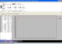
To get your minimum stated 240VDC you don't even seem to need the first cap (of CRCLCRC). Starting with an RC section using a 1.5 Ohm resistor and reverting to the 95uF cap for an RCLCRC filter gives you an output voltage of 240.41VDC with 4uV ripple. There is no overcurrent or voltage warning.
To get your minimum stated 240VDC you don't even seem to need the first cap (of CRCLCRC). Starting with an RC section using a 1.5 Ohm resistor and reverting to the 95uF cap for an RCLCRC filter gives you an output voltage of 240.41VDC with 4uV ripple. There is no overcurrent or voltage warning.
Dude! What you need is VMware or Parallels.
Or VirtualBox from Sun. Free for personal use.
dave
- Status
- Not open for further replies.
- Home
- Amplifiers
- Tubes / Valves
- need someone to run a sim in PSUD2...my PC is down and my MAC wont runt the program!!