Member
Joined 2009
Paid Member
Actually, I committed a great 'sin' on my TGM3 amplifier and used a couple of Tantalum electrolytics (one of them in parallel with the feedback cap) as I have been given a bunch of them. I have read that they are an interesting option, a) they are often used in military equipment because of their reliability, b) if you offend them with an over-voltage they burst into flames, c) they can impart some colour to the sound that some people find enjoyable, d) they perform well up to high frequencies.
Another comment I could make is with respect to the drivers. You have two output transistor pairs in parallel, I assume to allow a fairly high power output. These place a 'burden' on the drivers which have to drive their input impedances. The majority of your large signal distortion in the SS output stage will come from this limitation. You may not need to address this, it may be too little to worry about. But if you did want to address this, you could add pre-drivers, i.e. another pair of transistors placed before the existing driver devices, or you could use Sziklai pairs in place of your existing drivers; I did the latter in my last SS amp design.
Another comment I could make is with respect to the drivers. You have two output transistor pairs in parallel, I assume to allow a fairly high power output. These place a 'burden' on the drivers which have to drive their input impedances. The majority of your large signal distortion in the SS output stage will come from this limitation. You may not need to address this, it may be too little to worry about. But if you did want to address this, you could add pre-drivers, i.e. another pair of transistors placed before the existing driver devices, or you could use Sziklai pairs in place of your existing drivers; I did the latter in my last SS amp design.
Last edited:
Thanks Bigun,
I'm still confused about drivers and calculating the output stage I/V and keeping everything optimally loaded. I'll have to read up on that topic. But I'm sure I've seen a few popular amps use single drivers feeding an EF output stage with parallel output pairs. How serious is this concern?
The only reservation I have about using a pre-driver is (again) how to calculate the requirements. Any advice, or documentation you can point me towards?
Thanks!
..Todd
Gareth, Todd,
I don't put too much stock in the hard working drivers. When you look at the currents, they are small, and do not strictly warrant a triple EF if the driving impedance is reasonable, say with source impedance less than 50K.
Consider this: A load is 4R, voltage at peak is 42V. This is 220W into 4R, BTW, quite a bit of power. With two outputs, peak current will be 42/4 = 10.5A, presumably shared by two output devices, 5.25A each. If good devices such as C5200/A1943 are chosen, beta at this current will be around 100 (it's flat two decades from 70mA to 7A) so base drive for two devices will be 2 x 52.5mA = 105mA. Suitable drivers like C4793 and A1837) gain peak at 130 at this current, so the base drive to fire them up will be 105/130mA, which is just over 800 microamps. Not exactly a stiff load.... easy to drive with some finesse, in fact.
Typically, you'd use a bridging ratio of 10:1 at the drive circuit (usually the VAS collector) so this puts the quiescent current at this point around 8mA, give or take.
In fact these values work very well in practice. I've just described the figures used in the original AKSA 100W amp, and it never ran out of puff down to 2.5 ohm loads.
Now, driving a mosfet gate is a different matter. Here you need some real grunt at low source impedance to charge and discharge that pesky gate....
Cheers,
Hugh
Member
Joined 2009
Paid Member
As I said, I'm no sure how much benefit can be obtained from using the triple. What I can say is that my TGM3 was where I used a stronger driver topology for the first time and this amp sounded better than all that went before it. But I can't strictly say that the better sound was only due to the output topology as I had made some other changes.
AKSA is the expert here and if he says don't worry about using a triple, then I wouldn't worry about it. Of course, it could be fun to do the experiment and compare a double with a triple and see what you think with your own ears !
In terms of 'calculating' a triple, I'm not sure there's much to calculate. You could add another pair of drivers before the drivers you already have. What you can adjust is the q. current through them by adjusting the resistor connected between the emitters. You could stick with 220R for the pre-drivers and something lower (e.g. 47 Ohms) for the main drivers to allow them a bit more grunt (and put them on the heatsink). I haven't tried the triple EF topology, I used a CFP driver arrangement and allowed the CFP drivers to operate at a fairly healthy quiescent current - this ensures they have plenty of gain/slew rate.
p.s. agree with Hugh, you don't want MOSFETs unless it's a non-switching topology.
Last edited:
I have lot of experience with the triple EF, because I want to keep the tube stage as simple as possible. So I try to plan the amplifier to work with single common cathode stage. This is not possible without triple EF.
Than I made lot of listening to find the best components, and find the bias current for the devices.
The bias of the drivers was one of my most interesting experience. I allways believe that higher bias is better. But this is not true. 10mA is enough, if You use suck-out capacitor. There is no problem if You increase the current (I set it up to 200mA!), but no benefit. The only snag is the possible thermal runaway, due the higher dissipation of the drivers.
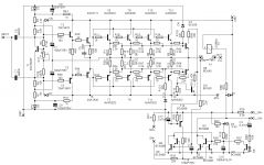
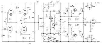
The schematic shows my results. Of course this works best only with the same parameters I used during the listening (such as the E88CC driver, with 3mA bias, and 50kohm anode resistor load).
The triple EF gives better bass response then double EF+cathode follower.
The CFP stage has nonlinear input impedance comparing to EF, this is not suitable for tube driver, only with low impedance circuit, such as White follower.
Sajti
Than I made lot of listening to find the best components, and find the bias current for the devices.
The bias of the drivers was one of my most interesting experience. I allways believe that higher bias is better. But this is not true. 10mA is enough, if You use suck-out capacitor. There is no problem if You increase the current (I set it up to 200mA!), but no benefit. The only snag is the possible thermal runaway, due the higher dissipation of the drivers.
The schematic shows my results. Of course this works best only with the same parameters I used during the listening (such as the E88CC driver, with 3mA bias, and 50kohm anode resistor load).
The triple EF gives better bass response then double EF+cathode follower.
The CFP stage has nonlinear input impedance comparing to EF, this is not suitable for tube driver, only with low impedance circuit, such as White follower.
Sajti
Hi Bigun and Hugh,
Thanks for the info. So adding 1 more output pair brings the drive current to 1.2 ma, which is, I assume, still reasonable? I'm thinking 3 output pairs is more suitable to the +-55v rails. Those devices you mentioned are the ones I had penciled in, Hugh.
Bigun, I will indeed compare it with triple EF. Why not.
I wouldn't consider doing this with MOSFETs since I know less about them than I do BJT's. And it's been done to death already (e.g. moskido).
Sajti, thanks for pitching in. I'm curious why you would want 4 output pairs with +-35V rails. That seems like overkill to me (needed for +-70V rails to be sure). Are you using any kind of delayed turn-on to avoid the tube warm-up time noise?
djk, I'll look at J. B.'s info, I hadn't (yet) considered using his board. I'm not sure where a 2nd coupling cap would be used. To inject signal into 2 places in the output section (ie. each end of the VBE multiplier)?
Thanks everyone. I'm learning lots.
..Todd
Last edited:
Sajti, thanks for pitching in. I'm curious why you would want 4 output pairs with +-35V rails. That seems like overkill to me (needed for +-70V rails to be sure). Are you using any kind of delayed turn-on to avoid the tube warm-up time noise?
Thanks everyone. I'm learning lots.
..Todd
Hi Todd,
because I use 2 of this module for each channel, bridged. The output power is about 400W/4ohms, and almost 700W/2ohms. So 4 pairs is necessary.
In the schematic You can see the loudspeaker, and overcurrent protection, which include the turn on delay as well. The delay time is 50sec.
Sajti
I'm not sure where a 2nd coupling cap would be used. To inject signal into 2 places in the output section (ie. each end of the VBE multiplier)?
..Todd
As You can see in my schematic.
Sajti
Member
Joined 2009
Paid Member
The triple EF gives better bass response then double EF+cathode follower.
Excellent - that tells you the triple is doing it's job - since bass tends to push the outputs to higher currents where beta droop is more prominent and where beefier drivers are the cure.
The CFP stage has nonlinear input impedance comparing to EF, this is not suitable for tube driver, only with low impedance circuit, such as White follower.
Is this from experience ? On the face of it I wouldn't agree with you since the driver stage presents an input impedance that reflects the input impedance of the output power devices it means the impedance is non-linear whether it be triple EF or CFP. The nice thing about CFP is that it's certainly more linear than a plain EF driver (with both operating in Class A) because of the local feedback.
Is this from experience ? On the face of it I wouldn't agree with you since the driver stage presents an input impedance that reflects the input impedance of the output power devices it means the impedance is non-linear whether it be triple EF or CFP. The nice thing about CFP is that it's certainly more linear than a plain EF driver (with both operating in Class A) because of the local feedback.
I have made some measurements. And the driver stage has higher distortion if the output was CFP, than EF. I used same transistors, with same bias, and same resistor values.
I don't know the reason.
Sajti
Member
Joined 2009
Paid Member
Interesting. Well a couple of thoughts. A CFP output stage is operating in ClassB. This isn't a good thing for CFP, it doesn't behave as well in a switching application as EF. One reason is that it's not possible to employ a charge suck-out cap in the usual way but it's also possible to prod it into oscillation this way. So I'd believe the CFP would be less desirable when used as an output (although other people have used it as such and been successful). I'm not proposing the use of CFP as the output. I'm proposing an EF output but with CFP drivers, where the CFP drivers are kept in Class A all the time. I believe this is a very good combination and it worked well for me in last SS amp. An EF output with CFP driver is akin to a triple in terms of overall current gain.
As You can see in my schematic.
Sajti
As I thought. Would my cap across the VBE multiplier still be required in this scenario? It seems kind of redundant.
..Todd
Sajti,
You make an interesting point about the triple; the very high input impedance which makes it easy for a common cathode tube to drive.
However, there are four options here to examine:
#1 OPS triple, driven by a CC tube with Zout of 25K or even higher (your preference);
#2 OPS DEF, driven by a CC tube followed by a direct couple cathode follower, then dual cap coupled to the top and bottom of the Vbe multiplier;
#3 OPS DEF, driven by a CC pentode like the 12GN7 which uses only a 4K load and delivers strong drive up to 100Vrms from B+ of 400V (see Pete Millett's circuit at Wheatstone Audio); or
#4 Wimpy plate loaded triode, say a 6DJ8/ECC88, driving a SS (mosfet OR bipolar) emitter follower which in turn drives the output stage, thus eliminating a push pull pair for a single ended drive element. You can then active load the emitter/source with a CCS for vanishingly low distortion so that distortion, all even order, is caused only by the Early effect.
My own preference would be to go for #4, because it's simple. If you have no global feedback, however, you would be obliged to use at least three output pairs, and use low value (0R15) emitter resistors for lowest possible Zout. In my experience with my zero gfb amp you must shoot for at most a Zout of around 0.33R. Any more, and you lose drive capacity with many loudspeakers.
Hugh
Last edited:
Hugh,
thanks for your point of view. May I give my notes:
#1: I use single triode driver, but with approx. 5kohms output impedance. This is E88CC with 3mA bias. Higher impedance tube is not enough to drive even triple darlington.
#2: Works, but only with high current cathode follower. In my experience is, that 12-18mA is necessary, to get same sound quality. I have used ECC99. SS predriver with 5mA easily do it.
#3: Can be good, but I have no experience with 12GN7 or other pentodes.
#4: It can be good as well. There are 2 possibilities:
a, The emitter follower is direct coupled to the common cathode stage. I don't like mosfets, and not easy to find BJT with good linearity, and high voltage.
b, The emitter follower is direct coupled to the output stage. In this case we need to use DC servo to keep the offset low. I have made this option, but unfortunately the quality was worse, than the triple ef. Maybe the servo was the reason, but I'm not shure.
The 0R22 emitter resistors make the bias stable. I will try to reduce them to 0R1, in the final version, to get lower output impedance.
The current amplifier has the output impedance is about 0.2ohms over the audio frequency range.
Sajti
Member
Joined 2009
Paid Member
As I thought. Would my cap across the VBE multiplier still be required in this scenario? It seems kind of redundant.
..Todd
You're right, the two approaches are both equivalent, you can use one interstage coupling cap and another cap across the Vbe multiplier or you can use two interstage coupling caps and no cap across the Vbe multiplier. There may be some minor benefits of one approach over the other but it more likely comes down to what you have in your 'junk box'. Using two interstage caps means you need two high voltage capacitors which for size and cost reasons means they are probably not very large. With only one interstage cap the other cap across the Vbe multiplier can be lower voltage and larger which may be better for low frequencies.
This thread is most interesting, there are really two designs in play now, one from Taj and one from Satji. I don't think we should mix them together because I think Taj wants something to learn and develop whilst Satji is looking to optimize a design based on prior experience.
You're right, the two approaches are both equivalent, you can use one interstage coupling cap and another cap across the Vbe multiplier or you can use two interstage coupling caps and no cap across the Vbe multiplier.
Got it. Thanks.
Hugh, do any of those scenarios apply to my schematic? I'm a bit confused by that. Am I providing a decent enough drive for the output section? I have a small assortment of common tubes I can use in the Aikido to optimize that drive. I had sort of planned on using 6N2P-EV or 6SL7 for the input pair and 6CG7 or 6SN7 for output, depending on which socket I pick up first. (Probably 9-pin since my selection is better -- I only have 1 6SL7.) But I have a bunch of others if something else makes more sense.
Here's an updated schematic...
..Todd
Attachments
Last edited:
Todd,
Absolutely fine. I make your gain around 28dB, close to the THX 29dB standard, using 6SL7 followed by 6SN7. There will be drive aplenty as Zout of the 6SN7 will be sub 1K.
You need about 100Vpp output at the tube to drive this amp to full power; with a B+ of 300V you should be able to pull around 180Vpp of clean output.
Go for it!!
Hugh
Member
Joined 2009
Paid Member
Given the different mu (i.e. gain) of the different tubes I wonder how much gain you need ? I suspect that because you have a SS output you don't need a lot of gain here since all the voltage gain will be passed on to the output stage. In most tube amps the output is a transformer which need large voltage swings but that doesn't apply here UNLESS you want extra gain to throw away on negative feedback.
Hugh's played with many more tubes than I but I am currently listening to a tube amp based on the octal 6SN7 and I like it a lot. The 6SN7 is widely available and is a proven and popular tube in terms of good sonics and they don't seem to suffer from microphonics either. There are different 'brands' to pick from so you can try different kinds in the future if you want. The 6SN7 is a medium-mu tube which may be plenty for your needs. It's also happy to work on the 150V that will be available (each tube sees only half of B+).
The 6SL7 is a higher mu tube and the penalty you pay there is higher internal resistance. There are even higher mu tubes and they can be unstable (parasitic oscillations) if not handled properly.
I reckon you'd do well if you built your amplifier with 6SN7 in all positions. Octal tube sockets are nice and big so easier to wire up and easier to keep heater wiring away from signal wiring (to avoid hum).
edit: posted before I saw Hugh's response...
Last edited:
- Status
- Not open for further replies.
- Home
- Amplifiers
- Solid State
- Aikido -> BJT/EF possible?