Don't laugh, I obviously have LOTS to learn about electronics.
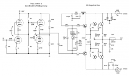
Is this configuration do-able? I've just copy/pasted John Broskie's Aikido pre-amp onto one of Carlos M.'s EF output stages. (I'll call it a "bi-kido".) I don't understand the biasing of either very well, but I'd appreciate some feedback as to whether this is even possible, or what it would require to make it possible.
Speaking of feedback, I have no idea where/how to insert feedback into the aikido section. My assumption would be at the input of the top 6SN7 triode.
..Todd
PS: Yeah, I see the output coil vanished, no big deal for now.
Attachments
Last edited:
Member
Joined 2009
Paid Member
Yes, it doesn't look good, the Vbe multiplier is fed from the +55C rail only. You could provide a resistor from emitter of the Vbe multiplier to the negative rail and adjust it for zero output but it's not ideal - it'll drift around with temperature variations. Still, it's doable (I've seen it implemented somewhat like this on a Yaqin hybrid). This resistor plus the coupling capacitor between the tubes and SS section will form an RC filter which shouldn't be a problem if you ensure that the coupling capacitor is large enough. If you are prepared to be a bit fancier you could implement a dc-servo with a simple op-amp.
Other thing you need to watch for here is that the tubes will take time to wake up from cold and you could end up with some ill defined signals appearing at the output which you might now want. A muting relay on the input to the SS output section would be advisable, something simple that holds the input to the SS output stage to ground until things are warmed up - could even be done with a JFET in place of a relay.
The input has no rf filter or dc blocking capacitor - if you are sure of your signal source this may be OK, but many people choose to incorporate a high quality small value cap on the input to protect the amp from dc at the source and sometimes include a RC filter to exclude r.f. interference at the input.
Last edited:
Other thing you need to watch for here is that the tubes will take time to wake up from cold and you could end up with some ill defined signals appearing at the output which you might now want.
I found the same with a valve/MOSFET amp I designed.
The coupling capacitor stops the output going to a rail but as the valve warms up the dc voltage rises and this is reflected as a low dc waveform at the output. This moves the cone in and out a bit.
I just set the dc blocking capacitor between valve and MOSFET stages to be just big enough and that reduced the dc swinging a bit.
This thread has a better bias stage.
http://www.diyaudio.com/forums/solid-state/164659-tube-mosfet-100w-hybrid-amplifier.html
http://www.diyaudio.com/forums/solid-state/164659-tube-mosfet-100w-hybrid-amplifier.html
Todd,
Nice idea, it should work, though not as you have the SS section due to biasing issues.
Perhaps one of the easiest ways to bias it up is two complementary bootstraps. Using, say, four 3k3 resistors, two in series from the positive rail to the top of the Vbe multiplier, and two in series from the negative rail to the bottom of the Vbe multiplier, you can derive a biasing totem pole by fine adjusting one of the 3k3 resistors to zero the output of the SS stage.
You then string two 220uF electros from the output, one to the middle of the upper two 3k3 resistors, and the other to the middle of the lower two 3k3 resistors.
This works well, has very high input impedance, and very stable offset control since the biasing totem is symmetrical across both rails, so rail voltage changes will be accommodated very nicely.
I have built and tested this approach and it is stable, predictable, and inexpensive.
Cheers,
Hugh
Member
Joined 2009
Paid Member
Speaking of feedback, I have no idea where/how to insert feedback into the aikido section. My assumption would be at the input of the top 6SN7 triode.
Try it without feedback first. You have to be careful with feedback here, you have an interstage capacitor and the feedback loop might also need one. This runs the risk of phase shifts at low frequencies since there's no dc-loop and the end result can be parasitic oscillations known as 'motorboating'
Oh, thanks for all the input, Bigun, Nigel and Hugh.
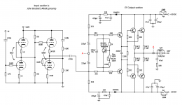
I've added an input cap, Bigun, and what I think you're suggesting, Hugh. Let me know if I got it right.
Nigel, that other thread is miles beyond my comprehension. So is this one but I'm willing to tough it out and try to learn a few more things.
..Todd
I've added an input cap, Bigun, and what I think you're suggesting, Hugh. Let me know if I got it right.
Nigel, that other thread is miles beyond my comprehension. So is this one but I'm willing to tough it out and try to learn a few more things.
..Todd
Attachments
Oh, thanks for all the input, Bigun, Nigel and Hugh.
I've added an input cap, Bigun, and what I think you're suggesting, Hugh. Let me know if I got it right.
Nigel, that other thread is miles beyond my comprehension. So is this one but I'm willing to tough it out and try to learn a few more things.
..Todd
The 470uF on the -55v rail is wired the wrong way round.
- to -55volts and + to gnd.

Just curious, what is the purpose of the 33R resistor and diode on the rails?
It's forming a subsonic RC low pass filter with the decoupling cap right? Then the 47nF is also working with the resistor to shunt out much higher frequencies? And the diode? Just some additional HW rectification? or protection of some sort?
..Todd
It's forming a subsonic RC low pass filter with the decoupling cap right? Then the 47nF is also working with the resistor to shunt out much higher frequencies? And the diode? Just some additional HW rectification? or protection of some sort?
..Todd
These filters remove crud from the rails, specifically half wave rectified ripple, which is created as the output stage alternately engages the load in push pull. It means as the rail sags, the diodes switch off, and the bias voltage, via the bootstrap resistors, maintain a constant current and do not inject noise into the output stage.
Hugh
Hugh
Member
Joined 2009
Paid Member
I'm not quite sure about that last schematic, it looks as if you have the interstage capacitor coupled to the same point as the bootstrap capacitors from the output. You have to make a couple more changes
a) move the connection point from the interstage capacitor to the emitter (or collector) of the Vbe multiplier
b) put a capacitor across the Vbe multiplier from emitter to collector (e.g. 22uF bipolar electrolytic) to ensure that the Vbe multiplier doesn't present an a.c. impedance between the inputs to the two halves of the output stage
Thanks Bigun,
I will change the signal injection point, but there's already a cap across the VBE multiplier, n'est pas? Granted, it's not currently bipolar, and a bipolar makes sense to me, but I regularly see polarized electros being used there; what gives?
..Todd
Last edited:
Member
Joined 2009
Paid Member
Yes, I didn't see the cap when I was checking your schematic this morning. I only suggested a bipolar because I believe they have lower distortion. The signal passes through this cap so it helps that it's good quality. Bipolar electrolytics are generally better than regular electrolytics in terms of audio. You can fake one by using two polarized electrolytics in series with their + (or -) terminals connected so they are back-to-back.
There are very few places in an amplifier where a capacitor doesn't 'see' the signal.
There are very few places in an amplifier where a capacitor doesn't 'see' the signal.
In this case there is a polarizing voltage of approximately 2.4V so a polarized cap is appropriate. Bigun has a point in for feedback caps where there isn't much if any polarizing voltage. Not to say that his experience preferring the sound of a bipolar here is wrong. Bipolars cost a bit more than polarized, and with 2.4VDC across the cap most designers will use a polarized cap
If you are worried about it, you can always add a film cap of 1 uf or so across the electrolytic.
If you are worried about it, you can always add a film cap of 1 uf or so across the electrolytic.
- Status
- This old topic is closed. If you want to reopen this topic, contact a moderator using the "Report Post" button.
- Home
- Amplifiers
- Solid State
- Aikido -> BJT/EF possible?