Nobody yet has pointed out that an all hollow-state
bridge rectifier would need THREE dedicated heater
windings that can float with the high and mid-high
voltages. In additon to 6.3V heater winding closer
to ground, for the rest of the cathodes...
A hybrid solution is really your best option for the
heater taps of your existing power transformer.
The two cathodes at the top can share a heater
winding. The two at the sides cannot....
Silicon Carbide Schottky has clean recovery like
glass. And the prices are finally getting reasonable.
Probably what I'd want in the lower half...
Last edited:
Nobody yet has pointed out that an all hollow-state
bridge rectifier would need THREE dedicated heater
windings that can float with the high and mid-high
voltages. In additon to 6.3V heater winding closer
to ground, for the rest of the cathodes...
By all hollow state, I assume you mean an all tube bridge rectifier? Right?
A hybrid solution is really your best option for the
heater taps of your existing power transformer.
The two cathodes at the top can share a heater
winding. The two at the sides cannot....
I am not sure what you mean about the two cathodes at the to and the two at the sides.
Silicon Carbide Schottky has clean recovery like
glass. And the prices are finally getting reasonable.
Probably what I'd want in the lower half...
I have been collecting parts and making another piece of art chassis for a GM70 amp and in my stash for that amp, I just found two Schottkys. They are MBR3045PT. Will those work? If so, I don't understand the scheme marked on the face of them. It shows the two directional arrows with lines across the tip both pointing inward to the center point. Can you help explain that?
Thanks for your help Ken.
djn:
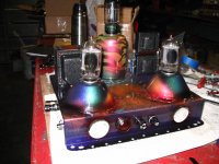
Serious work of art, man. I wish I had a tenth of your metalworing (and finishing) skills.
I'm following this thread closely; I'm designing a PS using 3b28s and dual chokes, and I'd rather run a hybrid than a quad of tubes.
Need lots of current - the PS will be running 6C33Cs. What's the current rule on chokes? Does each one have to be able to handle the full current load, or does that get split between multiple chokes.
The PS I'm working on in PSUII is punching out 800mA...
First, are the transformer and choke resistance values close? If not, adjust to match reality and model it with 4 vacuum rectifiers, then with 4 solid state ones. Average the two to see what you'll have with the hybrid bridge. BTW, I'd look for a HV secondary with less than 150 Ohms DCR for 100 mA.
Tom: How much of a difference should be seen when switching from tubes to SS? In PSUII I replaced the 3B28 bridge with a 1N4007 (no other changes made)...
3B28 - Max V 220.42; RMS 195.32
1N4007 - Max V 220.32; RMS 195.35
Is this to be expected, or did I perform a major screwup?
djn - apologies for the hijack...
Nobody yet has pointed out that an all hollow-state
bridge rectifier would need THREE dedicated heater
windings that can float with the high and mid-high
voltages. In additon to 6.3V heater winding closer
to ground, for the rest of the cathodes...
What nonsense! You can make an all hollow state bridge design by using a 5U4GB for the positive rail, and two 6DE4s for the negative. That will require the usual 5V/3A winding for the 5U4 (which most power xfmrs for hollow state already include) and one additional 6.3V/3.2A+ xfmr to run the 6DE4 heaters. Given that the Vhk rating for this type is 900Vdc, you likely won't even need to raise the heater xfmr secondary.
You see that particular design all the time in the schemos for vintage ham rigs. It's probably too much power supply for most audio amps, but there's no harm in having an over designed power supply anyway.
The only down side is: two extra holes to make, and additional heater xfmr. (That's why, for +/- supplies and bridges I prefer silicon -- it's a good deal cheaper and works just at least as well, if not a good deal better since you're not losing all that voltage across hollow state diodes.)
Tom: How much of a difference should be seen when switching from tubes to SS? In PSUII I replaced the 3B28 bridge with a 1N4007 (no other changes made)...
3B28 - Max V 220.42; RMS 195.32
1N4007 - Max V 220.32; RMS 195.35
Is this to be expected, or did I perform a major screwup?
djn - apologies for the hijack...
No problem. This is all good.
What nonsense! You can make an all hollow state bridge design by using a 5U4GB for the positive rail, and two 6DE4s for the negative. That will require the usual 5V/3A winding for the 5U4 (which most power xfmrs for hollow state already include) and one additional 6.3V/3.2A+ xfmr to run the 6DE4 heaters. Given that the Vhk rating for this type is 900Vdc, you likely won't even need to raise the heater xfmr secondary.
You see that particular design all the time in the schemos for vintage ham rigs. It's probably too much power supply for most audio amps, but there's no harm in having an over designed power supply anyway.
The only down side is: two extra holes to make, and additional heater xfmr. (That's why, for +/- supplies and bridges I prefer silicon -- it's a good deal cheaper and works just at least as well, if not a good deal better since you're not losing all that voltage across hollow state diodes.)
That kind of makes sense. So could he use the 6D22S instead of the 6DE4? I have a gagle of 6D22S laying about and might use them on my 807 PP amp.
djn:
Serious work of art, man. I wish I had a tenth of your metalworing (and finishing) skills.
I'm following this thread closely; I'm designing a PS using 3b28s and dual chokes, and I'd rather run a hybrid than a quad of tubes.
Need lots of current - the PS will be running 6C33Cs. What's the current rule on chokes? Does each one have to be able to handle the full current load, or does that get split between multiple chokes.
The PS I'm working on in PSUII is punching out 800mA...
Thanks Guiseppe, I am first and formost a metel sculptor so that is the real fun for me.
I had four 3B28 tubes for a project but I was talked out of using them by a bunch of people saying that, like the 866 merc rec tube, they can get very noisey but would still work with 4 of them or 2 in a hybrid configuration.
I don't know the current rules for choke, I just call my buddy Kegger and ask him if they will work.
800ma seems a little high. For my GM70 amp, I am using 250ma in PSUII and that was a very conservative over estimation..
I don't know the current rules for choke, I just call my buddy Kegger and ask him if they will work.
If you find out, could you post the info here? I'd appreciate it - I'm having problems finding information.
800ma seems a little high. For my GM70 amp, I am using 250ma in PSUII and that was a very conservative over estimation..
I was considering a PP using a pair of 6C33C-B, which are low-voltage, but current-hungry; from all the info I've been able to dig up, I'm planning to run them somewhere between 160 -200V, 220mA or so quiescent (general concensus seems to be 200V/220mA). By my estimates the circuit should draw a minimum of 440mA at idle, just for the 6c33s. Haven't drawn up load lines yet (haven't had the time), but a quick eyeball of the curves indicates that each tube could be drawing ~350mA @ Vg=-2V. I've drawn up a PS capable of pushing out 1A @200V using a quad of 3b28s without an issue - but that's max continuous current for those rectifiers in a full-wave or bridge config. Not sure if I want to push them that hard.
Again, I'm new to the tube scene - I think I'm on the right track... but I ain't betting on it.
edit - found some info on chokes in Jones' Valve Amplifiers, I'm wading thru it now...
Last edited:
I will also talk to Keg and relay what he says about chokes. we can compare notes. Yep, the 6C33C is very current hungry. I am collecting parts to build Tim Mellows 6C33C simple OTL and I noticed that the current of that tube is high. so you are probably in the ball park.
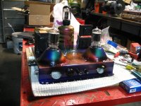
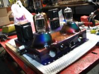
Maybe the 3B28 is quiter than the 866 but either one of them look REALLY COOL.
Maybe the 3B28 is quiter than the 866 but either one of them look REALLY COOL.
Jones doesn't mention anything about running chokes in series. Also, he mentions something about figuring an AC current component into the DC current (he broke out calculus; my eyes glazed over...). The longer I look at the PS I drew up, the more I'm starting to think I'll need a single choke - and a 10H choke capable of handling 800mA ain't gonna be cheap. More digging...
In that circuit, the chokes are pretty close to magic - plug them into the schematic, and the DC ripple just disappears...
Re 3b28 appearance: Oh, yeah. The 6c33c next to the 3b28 is pretty impressive.
I like big glass - especially when it's not 1KV big glass.
That kind of HV just makes me nervous...
Last edited:
Hey Joe, my eyes pretty much glaze over when I am thinking about any of this stuff. I consider myself a builder and rely on the experts. My OTL with the 6C33C is on a two teired chassis with the 4 6C33C on top and all the chokes, PTXs, and 3B28 tubes on the bottom.
I've not heard back from Keg yet on the chokes.
I've not heard back from Keg yet on the chokes.
I think I've seen pics of that chassis - should go a long way towards shielding the amp circuit tubes from any rectifier noise.
I can pretty much forget about a 10H 800mA choke - no such animal exists, at least as far as I can find. Largest I can find at that H rating is 500mA. I may need to redesign the entire PS - either parallel the chokes (can that even be done without blowing something up?), run each 6C33C from a seperate supply (more 3B28s, more chokes and other components, more chassis real estate, and more cash), or redesign without chokes.
Grrrr... must educate myself on the care and feeding of inductors.
..The longer I look at the PS I drew up, the more I'm starting to think I'll need a single choke - and a 10H choke capable of handling 800mA ain't gonna be cheap. More digging....
You can always trade off the choke inductance for larger capacitors and get the same result. Hammond makes a 1H 1A choke. If you buy modern radial lead caps they are cheaper than chokes for equal ripple reductions and at those high 800ma currents CLC is preferred over CRC because you loose less power. As the size of the caps get very large you have to plan on in-rush current but you can limit that with a thermistor or some other way.
Over the last few decades we see a shift for large chokes to large caps as the relative price of each has shifted. In the 40's a 20uf was "large" can not cheap but today a 220uf is affordable.
Chris: Many thanks. I've been working in PSUII for a few hours; the 1H chokes don't eliminate enough ripple, and I can't add enough uF to do the job without getting a current warning from the program. As I'm new at this, I'm pretty much stuck whatever PSUII has available - so I'm limited to playing with the more basic components. One piece of interesting news - Plitron indicates that their chokes can handle more DC current than their ratings suggest, provided that voltage is kept below the limit...
http://plitron.com/wp-content/uploads/http___www.plitron.com_audio_chokes2.pdf
The PAT4178 looks like it can handle ~720mA @200V - close to what I need (I think).
I'm going about this all wrong. I'm going to draw the loadlines for the 6C33C, figuring on a 1k2 output transformer for the pair in a PP, and work from there. I don't even know what I need - yet I'm trying to design a PS to fit.
No wonder I'm pulling my hair out.

the 1H chokes don't eliminate enough ripple, and I can't add enough uF to do the job without getting a current warning from the program.
There is a solution - model your PSU so that you get the ripple response you are looking for with the components you intend to use. Disregard the over-current situation at start-up as long as the stable running current is ok.
Now add a thermistor to the circuit. This will give you a sloooooooow start-up that is gentle on the rectifier etc, but gets out of the way after 10-20 seconds and lets the PSU run your full output.
Problem fixed.
I only heard of this thermistor technique since joining this forum. Is it simply connected at the output of the rectifier? If using split supply(for any reason) are two necessary?
Nicholas - I've got the same question. Seems it would make the most sense between the rectifier and the first choke or cap.
either in the primary OR the secondary. Logical place is actually the earth rail of the HVDC - lower voltage to worry about, but still in the series circuit and so adding total resistance to the circuit, but out of the heater circuit and other high current stuff
- Status
- Not open for further replies.
- Home
- Amplifiers
- Tubes / Valves
- will a PTX without center tap work?