Hello!
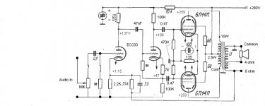
I built a tube amp like in attached schematics. I have those Russian 6p14p tubes and i decided to make a simple pp amp with them. I entered the audio signal to the grid of 6Z1P in schematics through 0.1uf capacitor. I used ECC83 in the first stage and phase splitter as well. The problem is that whatever i do, i get the clean output only to 1W@4 ohm on test load (2.1V AC). I measured the signal with windows based oscilloscope with soundcard (since i used it successfully with transistor amps, i can trust it somewhat 🙂. To the 1W the sine wave is clean, above that the sine wave get flattened like tubes limiting the signal effectively. Power supply voltage is 270V B+ with no signal and around 254 with this 1W out.
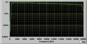
The frequency response is from 100hz to 19 khz (the gain is rising a little with frequency). Since i use cheap output transformer, its more than expected. Actually this circuit should work with negative feedback, but when i connected it to first stage cathode, the amp starts oscillating and no capacitor nor reducing the value of FB resistor thing would not work.
Can anybody suggest, how i can raise the output without raising the voltage of plates? This consruction should give at least clean 5w output which is my goal.
Thank you!
I built a tube amp like in attached schematics. I have those Russian 6p14p tubes and i decided to make a simple pp amp with them. I entered the audio signal to the grid of 6Z1P in schematics through 0.1uf capacitor. I used ECC83 in the first stage and phase splitter as well. The problem is that whatever i do, i get the clean output only to 1W@4 ohm on test load (2.1V AC). I measured the signal with windows based oscilloscope with soundcard (since i used it successfully with transistor amps, i can trust it somewhat 🙂. To the 1W the sine wave is clean, above that the sine wave get flattened like tubes limiting the signal effectively. Power supply voltage is 270V B+ with no signal and around 254 with this 1W out.
The frequency response is from 100hz to 19 khz (the gain is rising a little with frequency). Since i use cheap output transformer, its more than expected. Actually this circuit should work with negative feedback, but when i connected it to first stage cathode, the amp starts oscillating and no capacitor nor reducing the value of FB resistor thing would not work.
Can anybody suggest, how i can raise the output without raising the voltage of plates? This consruction should give at least clean 5w output which is my goal.
Thank you!
Attachments
One problem that I can see is that there is no power supply smoothing (resistor+capacitor to ground) between the 6Π14Π and the 6Ν2Π stage. This means that power supply noise signal is present on the anode of the 6Ν2Π. The noise is the output signal inverted. This is the first thing that "hit my eye". Try something like 2200Ω + 50 μF. About the feedback problem, you should connect the secondary of the output transformer in reverse. This will put the feedback in the correct phase.
1: Measure signal swing along its path (at the anode of first and second amplification stage, or after its coupling capacitor). Let us know what the readings say. Don't use sound card for that, use a propper voltmeter !
2: Feedback is applied to the second stage screen in your schematic, not first stage cathode. Have you followed the schematic or have you done something differently ?
3: If you have followed your schematic to the point and the amplifier is oscillating, you've probably taken the feedback signal from the wrong leg of the OPT secondary. Try using the other leg (you need to move ground connection as well) and report back.
With 1W output I would expect the amp to be still in Class A, so the B+ should not drop. Something wrong there? Are you sure the output transformers are what you think they are and that the load is correct.
One thing you should never give for granted is the feedback network. If you use a different OPT more likely it will not work very well.
Secondly, that phase-splitter is never really balanced! You should take the lower output from the cathode and not between the 2K2 and 47K resistors. I notice a diffuse misconception about the Zout's of this kind of splitter. They are the same if the anode load is equal to the cathode load. Of course if the two loads are not the same the two output signals will be not the same and this usually happens because of the output stage input impedance. Also this is true for ANY phase splitter.
So, to make it simpler, I would add a 2K2 in series with the anode resistor and take the lower output directly from the cathode. Try first without feedback. It should work decently at mid frequencies anyway....
45
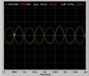
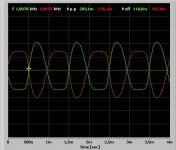
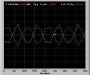
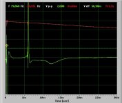
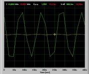
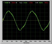
Thank you all for your suggestion! I attach the scope froms, everything regarding to the phase splitter should work. It is measured no 6P14P in place and from grid points. The voltmeter showed 0.6 volt both tube grids before clipping.The last frequency response and feedback graph is taken where the amp worked with dummy load. I tried also switch the OPT leads (old and good trick) between each other, still the same.
And now comes the point where everybody smashing big fist into my face 🙂. Im using 100V line transformer......because i ordered 30W UL transformers from US (good paper bobbin expensive OPT-s) and it takes at least one motnh to arrive to Estonia. I was just curious how the 100v line OPT-s perform.
Thank you again for your suggestions!
Attachments
One thing you should never give for granted is the feedback network. If you use a different OPT more likely it will not work very well.
Secondly, that phase-splitter is never really balanced! You should take the lower output from the cathode and not between the 2K2 and 47K resistors. I notice a diffuse misconception about the Zout's of this kind of splitter. They are the same if the anode load is equal to the cathode load. Of course if the two loads are not the same the two output signals will be not the same and this usually happens because of the output stage input impedance. Also this is true for ANY phase splitter.
So, to make it simpler, I would add a 2K2 in series with the anode resistor and take the lower output directly from the cathode. Try first without feedback. It should work decently at mid frequencies anyway....
45
If we want similar output impedance from the two output, wouldn't the extra output impedance introduced by connecting the lower output to the 47K help with that? Because the lower part is a cathode follower and the upper part is common cathode. In that case the effect of the different connections are minimal and the mis-match is impossible to cause such a big problem , like oscillation. In any case, I would say add a 2K2 on the anode side, but take the output from the juction of the lower 2K2 and the 47K.
But all this is for after you make it work...
No. You have equal outputs if you have the same loads for anode and cathode and take the outputs in the same way. If you take one output directly from the anode and the other at the junction of the 2K2 and 47K resistor the splitter is unbalanced and you get distortion.
The misconception is that people think that as one output is cathode follwer and the other is common cathote then the Zout's are different. This is true only if you take one output per time if you take both outputs simultaneously the Zout's and signals are the same (as long as the loads are the same).
The oscillation could be due to the OPT which is different and so that feedback network doesn't work. Also one could use grid stoppers for the output tubes or for all of them in the worst case.
45
You said that you connected the signal to the 6Z1P grid via a 0.1uF capacitor. Did you leave out the tone controls? If so, did you add a grid leak resistor for the 6Z1P? The original circuit does this via the bass tone control.
Please show us the circuit that you actually built.
Please show us the circuit that you actually built.
I attach the schematic which im currently working on. I need to apologize, because the original schematic differ from the current one. So i asked questions regarding to my current setup.
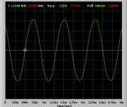
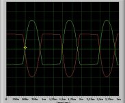
This circuit cannot be simpler and i alwayz try to make clear simple things first and then complex ones. The cathode follower was mentioned here and also resitor divider was the issue. When i connected lower 0.47uF cap directly to the cathode of the splitter, the signal was weaker than the anode signal. 2.2k resistor between 100k and cathode did the miracle! When i started this thread, i had the siganl connected directly to the cathode of the splitter. Now it works like a charm 🙂 Please take a look at the schematics and oscilloscope forms (100Hz, 1khz and 10khz). They have taken at full output power, which is now 6.4v AC, hence 6.4*6.4/4=10W!!!- Ten times more than before.
Only drawback that the feedback is still impossible to connect. The amp start oscillating. i think its due to my 10 dollars output transformers 😀. I cant wait to see this small amp working with real OPT-s.
I thank you all for contributing this topic, now im happy 🙂
Attachments
I attach the schematic which im currently working on. I need to apologize, because the original schematic differ from the current one. So i asked questions regarding to my current setup.
This circuit cannot be simpler and i alwayz try to make clear simple things first and then complex ones. The cathode follower was mentioned here and also resitor divider was the issue. When i connected lower 0.47uF cap directly to the cathode of the splitter, the signal was weaker than the anode signal. 2.2k resistor between 100k and cathode did the miracle! When i started this thread, i had the siganl connected directly to the cathode of the splitter. Now it works like a charm 🙂 Please take a look at the schematics and oscilloscope forms (100Hz, 1khz and 10khz). They have taken at full output power, which is now 6.4v AC, hence 6.4*6.4/4=10W!!!- Ten times more than before.
Only drawback that the feedback is still impossible to connect. The amp start oscillating. i think its due to my 10 dollars output transformers 😀. I cant wait to see this small amp working with real OPT-s.
I thank you all for contributing this topic, now im happy 🙂
Swap the plate leads on your output transformer and then try reconnecting the feedback..
Also is this really an OPT or a re-purposed speaker to line matching transformer as the schematic appears to hint at this.. With real OPTs you might get slightly more power and a lot better low end response.
Swap the plate leads on your output transformer and then try reconnecting the feedback..
Also is this really an OPT or a re-purposed speaker to line matching transformer as the schematic appears to hint at this.. With real OPTs you might get slightly more power and a lot better low end response.
Those transformers are 100V line transformers, not OPT-s. I ordered them from ebay and the guy there has built several guitar amps with them.
I tried to swap the plate leads as you suggested, nothing.
BTW, when i got output 10W as i previously posted, i attached the dummy load betwwen 4 ohm and 8 ohms. The common was attached to the amp pcb. So connecting everyhting as it should, the output is still 3 or 4W before sinewave gets ugly.
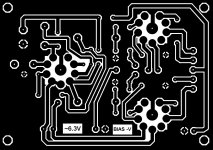
I also attach the pcb, if somebody interested. It has negative bias configuration, which i didnt use. I used two 270 ohm resistor to the 6P14P cathodes each with 220uF cap. So the voltage was 8.2v there, which means each output tube has ~30 mA plate currrent.
Attachments
I attach the schematic which im currently working on. I need to apologize, because the original schematic differ from the current one. So i asked questions regarding to my current setup.
This circuit cannot be simpler and i alwayz try to make clear simple things first and then complex ones. The cathode follower was mentioned here and also resitor divider was the issue. When i connected lower 0.47uF cap directly to the cathode of the splitter, the signal was weaker than the anode signal. 2.2k resistor between 100k and cathode did the miracle! When i started this thread, i had the siganl connected directly to the cathode of the splitter. Now it works like a charm 🙂 Please take a look at the schematics and oscilloscope forms (100Hz, 1khz and 10khz). They have taken at full output power, which is now 6.4v AC, hence 6.4*6.4/4=10W!!!- Ten times more than before.
Only drawback that the feedback is still impossible to connect. The amp start oscillating. i think its due to my 10 dollars output transformers 😀. I cant wait to see this small amp working with real OPT-s.
I thank you all for contributing this topic, now im happy 🙂
Are you sure about the voltage readings on that schematics? You cannot have 94V drop on 100K plate resistor and 47V drop on the 100K cathode resistor!
The current is the same. Resistors have some tolerance of course but a nominal 100K cannot be an actual 50K!
I think you have some issues if the phase splitter works in that configuration and doesn't work taking the output from the cathode. Never seen this.....
Maybe your output tubes (or your instrument) are not that good and cause troubles.
45
Last edited:
Im positive about the voltages in schematic (unless i have faulty DMM, which i dont believe). Voltages are measured when amp had full output. Then the voltage drop significantly down to 250v (i have 220v secondary).
Actually i got my feedback working. I removed pot and cap in front and connected audio directly to the grid with 1M resistor to the ground. Now it works without squeaks or anyhing. I use potentiometer for feedback and i can even gain it more when listening music. Output it is now 4,3v (clean sine wave). Yet i dont like the input without any cap......
I have headache already 🙂
Im positive about the voltages in schematic (unless i have faulty DMM, which i dont believe). Voltages are measured when amp had full output. Then the voltage drop significantly down to 250v (i have 220v secondary).
Usually voltages reported in schematics are DC voltages and thus they are supposed to be measured without signal. I think I stop right here......
Bye,
45
Usually voltages reported in schematics are DC voltages and thus they are supposed to be measured without signal. I think I stop right here......
Bye,
45
Sir,
I really need to apologize, because i found the problem and as alwayz because of my own stupidity. Like seen on my pcb, i have connected the phase splitter anode resistor to the left side of damping resistor 10k (it should be on the right side with 6p14p and B+). So therefore the voltages were like i reported. Actually the voltages were in idle state of course, not full power (I measured the power supply voltage at full power, which was dropped down, but this is unimportant).In other words, all that ECC83 voltages goes through 10k resistor, so it explains strange voltages 🙂. I attached my "unworking" schematic. It obviously mean that my amp cannot work. Im anxious to go home after work to try the "real" configuration.
Once again sir, my apologizes for fuzzy topic, but im newbie on this one and i should pay attention in the future.
Thank you!
Attachments
Sir,
I really need to apologize, because i found the problem and as alwayz because of my own stupidity. Like seen on my pcb, i have connected the phase splitter anode resistor to the left side of damping resistor 10k (it should be on the right side with 6p14p and B+). So therefore the voltages were like i reported. Actually the voltages were in idle state of course, not full power (I measured the power supply voltage at full power, which was dropped down, but this is unimportant).In other words, all that ECC83 voltages goes through 10k resistor, so it explains strange voltages 🙂. I attached my "unworking" schematic. It obviously mean that my amp cannot work. Im anxious to go home after work to try the "real" configuration.
Once again sir, my apologizes for fuzzy topic, but im newbie on this one and i should pay attention in the future.
Thank you!
You're not too proud to learn from your mistakes, and even better to admit to them in public.. You'll do well in the long run.. 😀
I would recommend getting some real opts and I think you will find that you have an even nicer sounding amp..
FWIW I long ago stopped using input capacitors in my amplifier designs, the output coupling cap in the line stage is supposed to take care of any dc issues, and I don't like more parts in the signal path than I absolutely need.
- Status
- Not open for further replies.
- Home
- Amplifiers
- Tubes / Valves
- 6P14P push pull with low output