I'm building a push-pull amplifier with balanced inputs.
Right now the only gain stage is a long tailed pair (with current source)
It works, but I need more gain (and i'm already using high-mu triodes).
I could simply add another pair of triodes and a current source, but something tells me there is a better way. (involving less current sources and coupling capacitors)
I have been searching for such a schematic/topology/.. but havent found one.
Anybody knows such a thing?
I'm building a push-pull amplifier with balanced inputs.
Right now the only gain stage is a long tailed pair (with current source)
It works, but I need more gain (and i'm already using high-mu triodes).
I could simply add another pair of triodes and a current source, but something tells me there is a better way. (involving less current sources and coupling capacitors)
I have been searching for such a schematic/topology/.. but havent found one.
Anybody knows such a thing?
Cascode LTP. Use high gm FETs on the bottom.
like he said; cascode - say isn't there some tube thingy with extra pins just so you can do that inside the bottle?
I need a lot of extra gain, pentodes wont cut it.
Cascode seems the way to go. I'll try to use some more triodes, as I dont have any jfets laying around..
Thanks guys!
Cascode seems the way to go. I'll try to use some more triodes, as I dont have any jfets laying around..
Thanks guys!
"current mode" ss can be exceptionally linear "open loop"
if you are gm limited rather than mu then cascode won't help - very much the the same as using pentodes
a ss current mirror load could do the trick if you're not too doctrinaire about tubes - large degeneration, beta canceling, cascoding output Q should give way better than -100 dB distortion of the mirror stage itself so arguments about "adding transistor character" are pretty weak
bjt ccs load are likewize very linear for push-pull
Last edited:
A cascode using a high-voltage MOS or BJT would work. If you have the headroom, you can rig a tube to do the same job. You should end up with a differential gain of 2*mu.
Umm.. But the current mirror has low input Z, so the tube stage itself will be distorting without it's internal voltage feedback. Same deal for cascodes, but cathode degen. can fix mostly.
By the way, what is actually needed here, more Mu or more voltage swing capability?
By the way, what is actually needed here, more Mu or more voltage swing capability?
Last edited:
very much the same as with cascodes or pentode - both "interrupt" the triode internal negative voltage feedback
current mirrors could also multiply output current, refer output to gnd
some circuit "complications" can improve stage linearity – even in no global feedback circuits - the "fewest devices" heuristic is naive
current mirrors could also multiply output current, refer output to gnd
some circuit "complications" can improve stage linearity – even in no global feedback circuits - the "fewest devices" heuristic is naive
Last edited:
I need a lot of extra gain, pentodes wont cut it.
Gee ! What are you trying to drive ?
A pair of 845 or 6550 cathode loaded 😀
Some pentodes exhibit Gm as hi as 40mA/V 😉
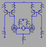
"current mirrors could also multiply output current, refer output to gnd"
Something like this? Maybe with a better mirror.
http://www.diyaudio.com/forums/tubes-valves/160776-phase-splitter-idea-2.html#post2077262
"some circuit "complications" can improve stage linearity – even in no global feedback circuits - the "fewest devices" heuristic is naive "
Kulish "Darlington" circuit for the bottom of a cascode or how about a Kulish version of a current mirror! Voltage input to current output, perfect. Super linear.
http://www.diyaudio.com/forums/tubes-valves/174792-kulish-circuit.html
Last edited:
Gee ! What are you trying to drive ?
A pair of 845 or 6550 cathode loaded 😀
Some pentodes exhibit Gm as hi as 40mA/V 😉
Should a pair of EF184's do it? I have tons of these, never actually designed a circuit wich uses them myself (or a small signal penthode in general)..
I'm trying to drive a pair of 807's in AB2
400V B+ and 300V on the screens (regulated)
I need about 80V peak according to the datasheet.
Right now I'm using two ECC88's in cascode. It certainly works better then the single 6N2 I tried earlier today 🙂
Looks like it's time for me to do some homework..
Last edited:
Don't forget that AB2 needs current as well as voltage drive. Most of the tricks to boost stage gain also increase output impedance. You will need a CF buffer too, or a beefy driver stage.
just a sketch - 5x mirror current gain - gives 5x Vgain with shown load R
lots of improvements to the current mirrors are possible
lots of improvements to the current mirrors are possible
Attachments
Last edited:
They should !Should a pair of EF184's do it? I have tons of these, never actually designed a circuit wich uses them myself (or a small signal penthode in general)..
With a Gm of 15mA/V and an input of 2Vpp (that is 0,7Vrms) you may expect 15mA swing in each tube since LTP spliter cuts the signal in half.
You could for exemple run them at 200V x 10mA (2WPd) and, from a 400V B+, the plate load resistor should be 20K and voltage swing will be (20 * 15) 300Vpp at each grid . . . very roughly !
I was a bit less ambitious, but this may help:I'm trying to drive a pair of 807's in AB2
400V B+ and 300V on the screens (regulated)
I need about 80V peak according to the datasheet.
. . .
6L6 Push Pull
Yves.
The current mirror looks very interesting too but it adds a lot of components i dont have at hand at the moment.
I might try it out on another project in the future..
Yvesm, thanks for the hints, i'll try it tomorrow or so.
Then i can put my 'new in box' philips ECC88's back into their box 😛 (I dont have enough ECC88's to build 2 monoblocks anyway)
Cool project Yves, I like how u used the ECF80 !
I might try it out on another project in the future..
Yvesm, thanks for the hints, i'll try it tomorrow or so.
Then i can put my 'new in box' philips ECC88's back into their box 😛 (I dont have enough ECC88's to build 2 monoblocks anyway)
Cool project Yves, I like how u used the ECF80 !
Kulish driver
A Kulish driver attached. V1 needs to have a significantly higher Mu than the final gain, or just use a small pentode. Q1 is a Mosfet. It may look like a Darlington, but it has much lower distortion due to the V1 current compensating for the Vgs distortion of the Mosfet. You might say that this circuit removes the Mosfet signature.
One could put a fixed voltage zener in series with R2 (nearly equal to, but less than, the Mosfet threshold Vgso) to lower V1 idle current. And finally, the circuit can also be used as a very linear follower, by taking the output off of Q1 source. No more complaints about Mosfet followers sounding SS. Vgs effects are removed.
Attachments
Last edited:
If you need a large amount of gain while retaining stability, chain a few common-cathode stages together, DC coupled if desired. Apply feedback to set gain to the desired level, reducing distortion to negligible amounts.
If you really need a serious amount of gain, several such amplifiers should be chained. This gives higher bandwidth and lower distortion than a single loop of extremely high gain (which will probably oscillate due to the extreme gain!).
This works great for SE or LTP. You can bias the grids/cathodes near a convienient rail if you wish (usually 0V). If you prefer grids or cathodes around 0V, you'll need a low current negative bias supply. You may already have one, if you're building a fixed-bias power amp. Otherwise, you can stand the cathodes on tail resistors, which is wasteful, but effective, and minimizes common mode error enough that you won't need a common-mode servo. (For SE, the cathode rail must be stabilized, e.g. with a power zener.)
Overall, a chain of stages looks just like an op-amp. Put a capacitor on one stage for dominant-pole compensation, and NFB around the whole thing to set the desired gain. Distortion will be negligible.
This Kulish driver is not well thought out. It looks like a hack someone tossed together carelessly. Vgk is in series with Vgs, so the nonlinear transconductance of both devices is added. There is no advantage in gain, because the triode's plate resistance contributes internal feedback. A pentode also has enough plate resistance to matter (in general, MOSFETs have much higher drain impedance than pentodes).
Ultimately, it truely is a darlington, which is a very bizarre use of relatively low transconductance, voltage-mode devices. This is a circuit which illustrates the worst characteristics of both tube and MOSFET. It should be stricken from the records and forgotten as so much tube folly.
BTW, the symbol labeled "MOSFET" is actually an IGBT symbol. I don't know of any IGBTs that would work well in such a use.
Tim
- Home
- Amplifiers
- Tubes / Valves
- long tailed pair - need more gain