Kean,
one would like to see the front end driven at say 10V higher than the rear end so that you can get the benefit of higher voltage swing from the back-end, hence my asking. As it satnds and you say 70V for the front end, what is the point of having 80V on the output devices.
one would like to see the front end driven at say 10V higher than the rear end so that you can get the benefit of higher voltage swing from the back-end, hence my asking. As it satnds and you say 70V for the front end, what is the point of having 80V on the output devices.
Hi Jam,
I would recommend two transformers as the current draw from one primary would affect the voltage available at the other tap. For the front end you are looking at a relatively small transformer, probably 2 VA, I would be op the opinion that it would be much more cost effective than winding a large toroidal with multiple windings as well as a better implementation.
Kean, my questions is not to test your capabilities or your technical skill, I am merely trying to make you consider as many practical implications as possible. Forget Goldmund with any or all their mistakes, it is not important - I take it this thread was to produce an amplifier of impeccable standard, not a revamp of something that left the market for whatever reason.
Hi Nico,
You have a point but I had thought of having seperate bridge rectifiers for each winding stacking them after rectification and regulating the high rails for the front end. I agree that the front should run of higher rails as you mentioned and I would opt for four pairs of output devices......you might want to bridge a pair of amps later.😎
Jam
Nico, I am glad for your attention. I can't worry about my skill being tested, no one benefits if I make bad design choices.
Is it possible we could rig up a Joule-thief type thing for the frontend?
To an extent we can't really determine the rail voltages for the real Goldmund with simulation. It used an odd CCS for the frontend, and because it will depend on transistor characteristics, we can't tell exactly what the stage current was without measuring the real thing. I guessed 4mA. But a small change in this will make a large change in VAS current. Without knowing the exact frontend current, we can't determine the upper rail voltage.
- keantoken
Last edited:
Well, one design choice is bugging me.
If we were to cascode the VAS to the bottom of R14, the amp's pulse behavior could be improved upon, as well as distortion. However, the spectrum would turn in favor of odd harmonics. Thoughts?
- keantoken
If we were to cascode the VAS to the bottom of R14, the amp's pulse behavior could be improved upon, as well as distortion. However, the spectrum would turn in favor of odd harmonics. Thoughts?
- keantoken
I think one would need to ask the question, what in the old Goldmund excited Nagy to call it what he did, is it the high slew (impulse response) or the 2nd order harmonic overshadows all others or is it the high rail volatges and running the amp on the brink of destruction or not matching devices and each doing its own thing. Indications are that the perfect sounding amplifier may be one that is technically flawed.
Kean the front end that is currently being decoupled by some form of regulation includes the differential amp, differential VAS and the drivers. I would think 50 mA may be adequate. Look at what is needed on the simulator place a zero ohm resistor in series with your power supply and measure the current through it.
If you were to take Jam's advice using a series CCS at say 80 - 100 mA and shunt regulator following it at the required voltage, there could be advantageous sound qualities according to some. I have not had an opportunity to listen to a shunt regulated amp but some say there may be magic hidden there.
I would still opt for running the front end at say 75 - 80V and the output stage at around the 65V mark. I tend to think no-one would perceive a difference in power output. But there would be a cost implication at 65V it would be cheaper.
the perfect sounding amplifier may be one that is technically flawed.
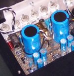
Any 250W amp with small size toroidals and 9400uF per channel is inherently technically flawed.
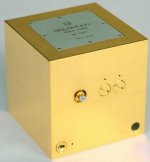
The perfect amp is goldplated.
Attachments
Last edited:
Indications are that the perfect sounding amplifier may be one that is technically flawed.
This is bad news for engineers! Or is it...
Kean the front end that is currently being decoupled by some form of regulation includes the differential amp, differential VAS and the drivers. I would think 50 mA may be adequate. Look at what is needed on the simulator place a zero ohm resistor in series with your power supply and measure the current through it.
I correctly guessed a value of 20mA, so my calculations should be accurate.
If you were to take Jam's advice using a series CCS at say 80 - 100 mA and shunt regulator following it at the required voltage, there could be advantageous sound qualities according to some. I have not had an opportunity to listen to a shunt regulated amp but some say there may be magic hidden there.
I would still opt for running the front end at say 75 - 80V and the output stage at around the 65V mark. I tend to think no-one would perceive a difference in power output. But there would be a cost implication at 65V it would be cheaper.
All in favor of 65V lower rails?
- keantoken
+-65Vdc does not allow one to use 63V capacitors.
~41Vac is about the maximum that can feed 63V caps.
45Vac needs to go to 75V or 80V caps.
~41Vac is about the maximum that can feed 63V caps.
45Vac needs to go to 75V or 80V caps.
All in favor of 65V lower rails?
Me thinks folks will be more Wowza'd by a 200W amp than 150.
Even 199 sounds less attractive to most, unless it's the sale tag.
Going down hill is easier than going up.
(provided this is not intended as just a mental exercise)
Well, we don't intend to sell it do we... Jacco? 😉
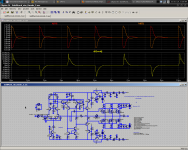
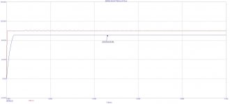
Here is the simulated slew rate currently. I don't know how much board layout is expected to cut into this.
Tanh, we all know your sims look good. But if you don't share, we can only ignore you!
- keantoken
Here is the simulated slew rate currently. I don't know how much board layout is expected to cut into this.
Tanh, we all know your sims look good. But if you don't share, we can only ignore you!
- keantoken
Attachments
Last edited:
Neuh, my favorite number is a C-note.
But it would be fun to see the prime Goldylock board endeavour go belly up by a bit of competitive marketing technique.
(btw : the heatsink of the Swiss original is insulated from the chassis, for good reason, if i may add)
But it would be fun to see the prime Goldylock board endeavour go belly up by a bit of competitive marketing technique.
(btw : the heatsink of the Swiss original is insulated from the chassis, for good reason, if i may add)
If at all possible, can the front end rails be kept at no more to than 100v for cap size and cost considerations?
I would still like to see 4 or more output devices, not for power, but for stability.
The confluence of an improvement of Goldmund and Something entirely different would suit me.
I would still like to see 4 or more output devices, not for power, but for stability.
The confluence of an improvement of Goldmund and Something entirely different would suit me.
The energy stored in a capacitor in joules increases as the square of the voltage / 2
E=C x V x V/2) So the Goldmund @ 2 x 4700uF 80 - 0 - 80V can manage 30 Joules total energy storage. Reduce this to 60 - 0 - 60 V rails and you need 2 x 8300uf just to equal the energy storage.
I can see that it would be practical to not exceed the voltage rating of the mosfets, but can not see the point in reducing the rail voltage below 75 - 0 - 75 - especially if it is proposed to increase the number of output pairs to 4.
Andrew has a point. Kean, toss a coin whether the rail should be 60 or 80V and adjust the front end 10V up from that. Then decide if a shunt regulator is the way to go and we take it from there.
Andrew has a point. Kean, toss a coin whether the rail should be 60 or 80V and adjust the front end 10V up from that. Then decide if a shunt regulator is the way to go and we take it from there.
+- 90 works for me in the fact we need as much before the output as possible.
I am still thinking about replacing the output laterals by a pair of Hitachi 2SK216/2sj79..driving 3 sets of BJT..outputs....Considering the large cost of the lateral output fets...this look like at proposition where you can get the most of both worlds...
possibly the 5 legged types from OnSemmi where the internal diode is used for bias spreading...and thermal tracking.
possibly the 5 legged types from OnSemmi where the internal diode is used for bias spreading...and thermal tracking.
Shunt
Hi Kean,
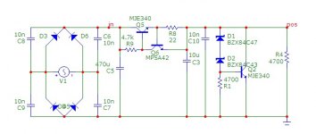
Here is a simple shunt regulator you can play with and enhance.
What we would need to consider is a speaker delay that will have a long enough time constant so that all the voltages in the amps stabilizes before connecting the speakers.
Hi Kean,
Here is a simple shunt regulator you can play with and enhance.
What we would need to consider is a speaker delay that will have a long enough time constant so that all the voltages in the amps stabilizes before connecting the speakers.
Attachments
- Home
- Amplifiers
- Solid State
- Goldmund Mods, Improvements, Stability