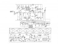
Same trick 'Zeck' use in this amplifier only single pair laterals.
And current thru the laterals is under 1A at full power😉
Apex,
I like your output stage, I have used mosfets to drive full comp. bipolar stage with good results, Some thing that needs to be explored more.'
Jam
Apex,
I think the main idea of the circuit is to EXTEND the power of LMOSFET output. The sound character/quality is of course cannot be better than the output from the FET's source. When sound quality has to be compromised by price consideration, it is difficult to comment. But for this topology, I'm interested in a "normal" power, with sound quality being paid more attention.
(1) First job I think is to choose the MOSFET: The toshiba, LFET, VFET
(2) Source follower or drain follower
I'm interested in a paralleled IRF610/9610 (200V/3A device) in drain follower configuration. I haven't seen it, but don't know why it has not been tried? Matching issue?
And I'm more interested in LMOSFET output stage driven by the above IRFs.
Well, that is if I can design an amp hehe 😀
Main idea is to extend the power of lmosfet output, but sound is different, dumping factor of this topology can't be the same as all laterals output. I never use IGBT outputs, and this 'Zeck' schematic give me some ideas...
I see a Pi filter on the output using R35, 36, 37, L1, C19, 20.Don't forget HAFLER9300 and DH220.
This is the first time I have seen the full Thiele Network in the Pi format that I have been advocating.
Can someone supply component values?
Last edited:
I see a Pi filter on the output using R35, 36, 37, L1, C19, 20.
This is the first time I have seen the full Thiele Network in the Pi format that I have been advocating.
Can someone supply component values?
R35 = 10R
R36 = 1R
R37 = 10R
C19 = 10nF
C20 = 100nF
L1 = 1,4uH
output Thiele Pi filter Network
R35 = 10r
R36 = 5r
R37 = 5r
C19 = 47nF
C20 = 68nF
L1 = 1uH
I have arrived at similar but different.R35 = 10R
R36 = 1R
R37 = 10R
C19 = 10nF
C20 = 100nF
L1 = 1,4uH
R35 = 10r
R36 = 5r
R37 = 5r
C19 = 47nF
C20 = 68nF
L1 = 1uH
I have arrived at similar but different.
R35 = 10r
R36 = 5r
R37 = 5r
C19 = 47nF
C20 = 68nF
L1 = 1uH
You are right, I use part list from DH500.
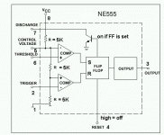
Protect circuit with NE555 use separate 12v ac, and can be use for any amp.
Attachments
Last edited:
it is not "right or wrong".You are right, I use part list from DH500.
I am simply pointing out that different values can be used.
it is not "right or wrong".
I am simply pointing out that different values can be used.
I agree, it's just wrong value on part list for DH200.
'Zeck' use this unusual output stage in some amplifiers. NE555 is use for protect.
It is kind of "Current Dumping".
It is kind of "Current Dumping".
No it's not 'current dumping' amp, adventage of this output stage is useing the best from lateral MOSFETs and BJTs, I'm wondering why this circuit not used more often and NE555 for protect... 😎
Last edited:
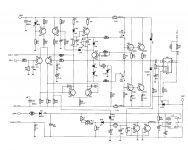
No, it is not "Current Dumping" amp, but it is kind of "Current Dumping". This exact circuit is not used, but this and similar arrangement of output devices is used. I myself used more complex arrangement: single ended class A driving speaker through resistor and degraded emitter followers and source followers in parallel. I.e. 3'step approximation: class A, then degraded class C using BJTs, then toothcrushing class C MOSFETs.
No, it is not "Current Dumping" amp, but it is kind of "Current Dumping". This exact circuit is not used, but this and similar arrangement of output devices is used. I myself used more complex arrangement: single ended class A driving speaker through resistor and degraded emitter followers and source followers in parallel. I.e. 3'step approximation: class A, then degraded class C using BJTs, then toothcrushing class C MOSFETs.
Can You share your schematic?
Can You share your schematic?
I have to search. I shared it about 4 years ago, I don't remember the thread name...
- Status
- Not open for further replies.
- Home
- Amplifiers
- Solid State
- MOSFET/BJT QUASI AMPLIFIER WITH PROTECT!!!