Gday Everyone,
I asked some questions a while back about an issue with a guitar amp, which I got some very good help with.
Unfortunatley my knowledge regarding valve amplifiers needed a big boost so I have bought a book & have been studying a lot before asking any more questions about the amplifier mentioned above.
I have a question about directly heated cathode rectifier valves, in this case a 5Y3GT rectifier valve.
This is going to be a real newby question but here goes.
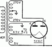
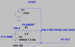
I have attached a picture of a 5Y3GT wiring diagram & also a picture of a quick LTSPICE simulation of the same valve to try to understand a bit more on this.
In the picture of the Simulation, V1 is the Rectified DC voltage from Pin 2 on the valve, R1 is the Heater Filament.
V2 is the Heater Filament supply voltage 15V Peak to Peak--5.1V RMS.
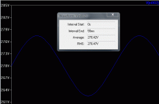
When I run the simulation I still get the 15V peak to peak signal but now the RMS voltage is around 270V on PIN 8 of the valve.
I am a little confused with this?
Ok, this is still a 15V peak to peak voltage but the RMS voltage is a lot higher than the 5.1V?
Could someone explain this for me, am I just looking at it all wrong or do I have the simulation etc all buggered up?
Cheers
Attachments
Last edited:
Hi hidnplayr,
Yes I get 270v out but I also get 270V RMS back onto pin 8 of the valve which is what I thought would happen, that's why I did the simulation & hence the confusion about it?
Cheers
Yes I get 270v out but I also get 270V RMS back onto pin 8 of the valve which is what I thought would happen, that's why I did the simulation & hence the confusion about it?
Cheers
Oh i see what you mean now..
The 5V supply is at +270V potential.
There is no problem with that, just dont use it for something else then the rectifier.
I really dont see your problem
The 5V supply is at +270V potential.
There is no problem with that, just dont use it for something else then the rectifier.
I really dont see your problem
Thanks hidnplayr,
I think the problem I have is just a lack of full understanding at this stage.
I think you have just answered my question with:
"The 5V supply is at +270V potential."
Yes. I see what you mean, well I think I do?
If I had say 350V RMS at pin 8 then I would still have the 5V supply but at +350V potential.
Is that correct?
Cheers
Yes your 5V supply has 350VDC superimposed on it but there is still only 5V AC applied to the heater, that is why there is a separate winding on the transformer for it not to mention AFAIK only directly heated valves use 5V heaters. In the days of valve televisions the heater of the 1S2 EHT rectifier had 15KvDC imposed on its 1.4V heater.
Thanks metalsculptor,
The reply from yourself & replies from hidnplayr have been very useful.
I actually have some new & used 1S2 valves & have seen the high voltages on the datasheets. Not sure i'll ever use them though!
Thanks again for the replies.
Cheers
The reply from yourself & replies from hidnplayr have been very useful.
I actually have some new & used 1S2 valves & have seen the high voltages on the datasheets. Not sure i'll ever use them though!
Thanks again for the replies.
Cheers
AFAIK only directly heated valves use 5V heaters.
The 5AR4 is indirectly heated..........
Splitting "frog hairs", the 5AR4, 5V4, 6106 ... are 1/2 indirectly heated. While they contain cathode sleeves, said sleeves are tied to the heater at pin 8. That construction style dodges the issue of heater to cathode potential limit.
Best results, hum wise, are obtained from 1/2 indirectly heated types by taking the B+ from pin 8. OTOH, the lowest hum is obtained from directly heated types by taking the B+ off a CT on the 5 VAC winding.
If you want to experiment with swapping between a 5AR4 and a 5U4, take the B+ off of pin 8.
Best results, hum wise, are obtained from 1/2 indirectly heated types by taking the B+ from pin 8. OTOH, the lowest hum is obtained from directly heated types by taking the B+ off a CT on the 5 VAC winding.
If you want to experiment with swapping between a 5AR4 and a 5U4, take the B+ off of pin 8.
5AR4 is a new one on me in Australia 5V4, 80 5U4 5Y3 and 6X4 were the usual low power rectifiers with 833A's used in medium power applications. quite a few power transformers had centre tapped 5V windings, I am relying on my recollection of stuff almost 30 years ago. I used to collect valves and valve radios in my younger days pity I didn't have my collection now.
Metalsculptor,
You may know the 5AR4 as the GZ34. Mullard made some of the best, ever.
At 70 mA. of B+, the 6X4 is really for preamps. The 6CA4/EZ81 is good for 150 mA., while the 6V4/EZ80 falls between the 6X4 and 6CA4 in capability.
You may know the 5AR4 as the GZ34. Mullard made some of the best, ever.
At 70 mA. of B+, the 6X4 is really for preamps. The 6CA4/EZ81 is good for 150 mA., while the 6V4/EZ80 falls between the 6X4 and 6CA4 in capability.
Cheers Eli
The GZ34 rings a bell but I have never seen one the 6X4 was popular in mantle radios in Australia.
Oops I meant 872A in my previous post not the 833A which AFAIR is a strange looking double top cap power triode. There is a small mercury arc diode good for about 1/2 amp which covers the range between the vacuum rectifiers and the 872A whose name eludes me, I have some in a machine but getting to it is a bit difficult at present. The real fun things to see operating are mercury pool rectifiers
- Status
- Not open for further replies.
- Home
- Amplifiers
- Tubes / Valves
- Rectifier Valves


