What follows is preliminary and probably has a mistake or two that I have not found yet. For the purposes of clarity, additional parentheses have been added to the formula. Any corrections needed are welcomed.
Regards,
WHG
Given:
[Rt] - Radius of Driver Exit & Horn Entry ...{06}
[At] - Flare Slope Angle at Driver Exit / Horn entry
= Atan([Mt]) ... [01]
[Mt] - Flair Slope at Driver Exit
= Tan[At] ... [02]
[Ac] - Horn Coverage Angle
= Atan([Mc]) ...[03]
[Mc] - Slope of Coverage Asymptote
= Tan[Ac] ...[04]
[L] - Length of Horn Profile
Find
[Lt] - Length of Horn Profile where its Slope Angle = [At] ...{15}
[Ro] - Radius of Horn Profile at [L] = 0 ...{18}
For
[Rl] - OS-Horn Radius at Profile Length [L]
= {([Mc]^2)*([L]^2)+([Ro]^2)}^(1/2) ...[05]
Characterize [Ro] in Terms of [Rt], [Lt] & [Mc]
[Rt] = {([Mc]^2)*([Lt]^2)+[Ro]^2}^(1/2) ...[06]
[Rt]^2 = ([Mc]^2)*([Lt]^2)+[Ro]^2 ...[07]
[Ro]^2 = -([Mc]^2)*([Lt]^2)+[Rt]^2 ...[08]
Characterize [Ro] in Terms of [Mt] & [Lt] & [Mc]
[Mt] = (([Mc]^2)*[Lt])/((([Mc]^2)*([Lt]^2)+([Ro]^2))^(1/2)) ...[09]
[Mt]^2 = (([Mc]^4)*[LT]^2)/(([Mc]^2)*([Lt]^2)+[Ro]^2) ...[10]
([MC]^2)*([LT]^2)+([Ro]^2) = (([Mc]^4)/([Mt]^2))*([LT]^2) ...[11]
([Ro]^2) = ((([Mc]^4)/([Mt]^2))-([MC]^2))*([LT]^2) ...[12]
From [08] & [12] Solve for [Lt]
([Mc]^4)/([Mt]^2))*([Lt]^2)=[RT]^2 ...[13]
[Lt]^2 = ([Rt]^2)*([Mt]^2)/([Mc]^4) ...[14]
[Lt] = {([Rt]^2)*([Mt]^2)/([Mc]^4)}^(1/2) ...[15]
From [08] & [14] Solve for [Ro]
[Ro]^2 = -([Mc]^2)*([Rt]^2)*([Mt]^2)/([Mc]^4)+([Rt]^2) ...[16]
[Ro]^2 = ([Rt]^2)*(1-([Mt]^2)/([Mc]^2)) ...[17]
[Ro] = [Rt]*{(1-([Mt]^2))/([Mc]^2)}^(1/2) ...[18]
*Update/Corrections
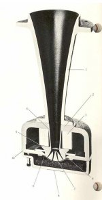
Smooth Joint Connection of an OS-Horn to a Compression Driver
What follows is preliminary and probably has a mistake or two that I have not found yet. For the purposes of clarity, additional parentheses have been added to the formula. Any corrections needed are welcomed.
Regards,
WHG/09-Oct-10
*Update/Corrections
WHG/09-Oct-10
Given:
[Rt] - Radius of Driver Exit & Horn Entry ...{06}
[At] - Flare Slope Angle at Driver Exit / Horn entry
= Atan([Mt]) ... [01]
[Mt] - Flair Slope at Driver Exit
= Tan[At] ... [02]
[Ac] - Horn Coverage Angle
= Atan([Mc]) ...[03]
[Mc] - Slope of Coverage Asymptote
= Tan[Ac] ...[04]
[L] - Length of Horn Profile
Find
[Lt] - Length of Horn Profile where its Slope Angle = [At] ...{15}
[Ro] - Radius of Horn Profile at [L] = 0 ...{18}
For
[Rl] - OS-Horn Radius at Profile Length [L]
= {([Mc]^2)*([L]^2)+([Ro]^2)}^(1/2) ...[05]
Characterize [Ro] in Terms of [Rt], [Lt] & [Mc]
(Recast [05].)*
[Rt] = {([Mc]^2)*([Lt]^2)+[Ro]^2}^(1/2) ...[06]
[Rt]^2 = ([Mc]^2)*([Lt]^2)+[Ro]^2 ...[07]
[Ro]^2 = -([Mc]^2)*([Lt]^2)+[Rt]^2 ...[08]
Characterize [Ro] in Terms of [Mt] & [Lt] & [Mc]
(1st. Derivative of [06].)*
[Mt] = (([Mc]^2)*[Lt])/((([Mc]^2)*([Lt]^2)+([Ro]^2))^(1/2)) ...[09]
[Mt]^2 = (([Mc]^4)*[LT]^2)/(([Mc]^2)*([Lt]^2)+[Ro]^2) ...[10]
([MC]^2)*([LT]^2)+([Ro]^2) = (([Mc]^4)/([Mt]^2))*([LT]^2) ...[11]
([Ro]^2) = ((([Mc]^4)/([Mt]^2))-([MC]^2))*([LT]^2) ...[12]
From [08] & [12] Solve for [Lt]
([Mc]^4)/([Mt]^2))*([Lt]^2)=[RT]^2 ...[13]
[Lt]^2 = ([Rt]^2)*([Mt]^2)/([Mc]^4) ...[14]
[Lt] = [Rt]*[Mt]/([Mc]^2) ...[15]*
From [08] & [14] Solve for [Ro]
[Ro]^2 = -([Mc]^2)*([Rt]^2)*([Mt]^2)/([Mc]^4)+([Rt]^2) ...[16]
[Ro]^2 = ([Rt]^2)*(1-([Mt]^2)/([Mc]^2)) ...[17]
[Ro] = [Rt]*{1-([Mt]^2)/([Mc]^2)}^(1/2) ...[18]*
Thumbnail Added
Smooth Joint Connection of an OS-Horn to a Compression Driver
What follows is preliminary and probably has a mistake or two that I have not found yet. For the purposes of clarity, additional parentheses have been added to the formula. Any corrections needed are welcomed.
Regards,
WHG/09-Oct-10
*Update/Corrections
WHG/09-Oct-10
Given:
[Rt] - Radius of Driver Exit & Horn Entry ...{06}
[At] - Flare Slope Angle at Driver Exit / Horn entry
= Atan([Mt]) ... [01]
[Mt] - Flair Slope at Driver Exit
= Tan[At] ... [02]
[Ac] - Horn Coverage Angle
= Atan([Mc]) ...[03]
[Mc] - Slope of Coverage Asymptote
= Tan[Ac] ...[04]
[L] - Length of Horn Profile
Find
[Lt] - Length of Horn Profile where its Slope Angle = [At] ...{15}
[Ro] - Radius of Horn Profile at [L] = 0 ...{18}
For
[Rl] - OS-Horn Radius at Profile Length [L]
= {([Mc]^2)*([L]^2)+([Ro]^2)}^(1/2) ...[05]
Characterize [Ro] in Terms of [Rt], [Lt] & [Mc]
(Recast [05].)*
[Rt] = {([Mc]^2)*([Lt]^2)+[Ro]^2}^(1/2) ...[06]
[Rt]^2 = ([Mc]^2)*([Lt]^2)+[Ro]^2 ...[07]
[Ro]^2 = -([Mc]^2)*([Lt]^2)+[Rt]^2 ...[08]
Characterize [Ro] in Terms of [Mt] & [Lt] & [Mc]
(1st. Derivative of [06].)*
[Mt] = (([Mc]^2)*[Lt])/((([Mc]^2)*([Lt]^2)+([Ro]^2))^(1/2)) ...[09]
[Mt]^2 = (([Mc]^4)*[LT]^2)/(([Mc]^2)*([Lt]^2)+[Ro]^2) ...[10]
([MC]^2)*([LT]^2)+([Ro]^2) = (([Mc]^4)/([Mt]^2))*([LT]^2) ...[11]
([Ro]^2) = ((([Mc]^4)/([Mt]^2))-([MC]^2))*([LT]^2) ...[12]
From [08] & [12] Solve for [Lt]
([Mc]^4)/([Mt]^2))*([Lt]^2)=[RT]^2 ...[13]
[Lt]^2 = ([Rt]^2)*([Mt]^2)/([Mc]^4) ...[14]
[Lt] = [Rt]*[Mt]/([Mc]^2) ...[15]*
From [08] & [14] Solve for [Ro]
[Ro]^2 = -([Mc]^2)*([Rt]^2)*([Mt]^2)/([Mc]^4)+([Rt]^2) ...[16]
[Ro]^2 = ([Rt]^2)*(1-([Mt]^2)/([Mc]^2)) ...[17]
[Ro] = [Rt]*{1-([Mt]^2)/([Mc]^2)}^(1/2) ...[18]*
Attachments
WIP
Hi Ed,
I have an Excel sheet as well that was published on the web about 10-Years ago.
Just adding Freehafer's horn to it. So published the work here for others to use.
Like most other horns, it needs a Tractrix bell termination to make it finite.
A smooth match can be implemented as well by applying the same math regimen presented here.
Check your private e-mail for my address.
Regards,
Bill
There is an excel worksheet available for this.
You have pm requesting your address.
Hi Ed,
I have an Excel sheet as well that was published on the web about 10-Years ago.
Just adding Freehafer's horn to it. So published the work here for others to use.
Like most other horns, it needs a Tractrix bell termination to make it finite.
A smooth match can be implemented as well by applying the same math regimen presented here.
Check your private e-mail for my address.
Regards,
Bill
WIP2
Bill,
Hi Ed,
In your spredsheet, calculate [Lt] and [Ro] from [Rt] and [Mt] (or [At]) using the formula [15] and [18] provided here earlier.
Then recast formula [05] to
[Rl] - OS-Horn Radius at Profile Length [L]
= {([Mc]^2)*(([Lt]+[L])^2)+([Ro]^2)}^(1/2) ...[19]
Now the horn graph will start at the desired attachment point of [L]=0,[Rl]=[Rt] .
I will have an update shortly that will add a tractrix bell and refine the formula given here. These you may incorporate into your spreadsheet as well. I prefer horns with elliptical, rectangular, or 'bow tie' apertures, rather than those with circular boundaries that extend beyond the throat. This preference is based on the shape of the space being irradiated (typically of rectangular section) and the distribution of listeners to be covered within. Ideally the OS horn flair should be incorporated into the phase plug design of its accompanying compression driver. Presently most available drivers employ an exponential flair; so at best, the resulting combination yields a hybrid horn.
Regards,
Bill
Tractrix Bell
To terminate Freehafer's OS Horn with a Tractrix Bell,
Let
[Ln] - Length of OS Horn Neck
Then
[Rn] - Radius of OS Neck at [Ln]
= SqRt(([Mc]^2)*([Ln]^2)+([Ro]^2)) ...[20]
[Mn] - Slope of OS Neck at Point [Ln],[Rn]
= ([Mc]^2)*[Ln]/SqRt(([Mc]^2)*([Ln]^2)+([Ro]^2)) ...[21]
[Mb] - Slope of Tractrix Bell at Point [Ln],[Rn] ...[22]
= [Rn]/SqRt(([Rm]^2)-([Rn]^2))
[Rm] - Radius of Tractrix Bell Mouth
= SqRt(([Mn]^2)+1)*[Rn]/[Mn] ...[23]
[Lb] - Length of Tractrix Bell
= [Rm]*LN(([Rm]+SqRt(([Rm]^2)-([Rn]^2)))/[Rn])-SqRt(([Rm]^2)-([Rn]^2)) ...[24]
Comments, corrections, and additions by others are welcome.
Regards,
WHG
Last edited:
For some drivers it should be possible to machine a new throat of simple cylindrical cross section and have the OS flare solely in the waveguide section. I wonder how this would affect the polar response and HOMs.Ideally the OS horn flair should be incorporated into the phase plug design of its accompanying compression driver. Presently most available drivers employ an exponential flair; so at best, the resulting combination yields a hybrid horn.
Regards,
Bill
Contraindicated
For three reasons that come to mind:
[1] The geometry of the phase plug will still remain flared and cannot be machined in the way you suggest. So in this case, a discontinuity is now introduced between the phase plug exit and the horn connection.
In the region where signal wavelength becomes comparable to cylinder dimensions, additional ripple in frequency response will be introduced for a variety of reasons. Depending on the upper frequency limit objective for a particular design, this may or may not be important.
[2] To perform the machining of the throat will require driver disassembly to prevent metal fragments from entering the compression chamber and magnetic gap that would otherwise destroy the driver when subsequently operated.
[3] In any case, such modification of the driver will void the manufacturer’s warranty.
Regards,
WHG
For some drivers it should be possible to machine a new throat of simple cylindrical cross section and have the OS flare solely in the waveguide section. I wonder how this would affect the polar response and HOMs.
For three reasons that come to mind:
[1] The geometry of the phase plug will still remain flared and cannot be machined in the way you suggest. So in this case, a discontinuity is now introduced between the phase plug exit and the horn connection.
In the region where signal wavelength becomes comparable to cylinder dimensions, additional ripple in frequency response will be introduced for a variety of reasons. Depending on the upper frequency limit objective for a particular design, this may or may not be important.
[2] To perform the machining of the throat will require driver disassembly to prevent metal fragments from entering the compression chamber and magnetic gap that would otherwise destroy the driver when subsequently operated.
[3] In any case, such modification of the driver will void the manufacturer’s warranty.
Regards,
WHG
1) If we can assume that the wave produced after the transformation through the phase plug is planar (unfortunately not usually the case), a simple tube should not change the sound wave at all, yes?For three reasons that come to mind:
[1] The geometry of the phase plug will still remain flared and cannot be machined in the way you suggest. So in this case, a discontinuity is now introduced between the phase plug exit and the horn connection.
In the region where signal wavelength becomes comparable to cylinder dimensions, additional ripple in frequency response will be introduced for a variety of reasons. Depending on the upper frequency limit objective for a particular design, this may or may not be important.
[2] To perform the machining of the throat will require driver disassembly to prevent metal fragments from entering the compression chamber and magnetic gap that would otherwise destroy the driver when subsequently operated.
[3] In any case, such modification of the driver will void the manufacturer’s warranty.
Regards,
WHG
2) Of course. I wasn't even thinking of machining the existing part or assembly but rather making another one and swapping out the factory part.
3) Isn't that the whole point?
I have made a wooden taper, attached sand paper and used it to remove the mold marks within the throat of the B & C DE250. I then used it to match/smooth the transition to the QSC 152i waveguide.
Sanding plastic in a "confined" space required frequent cleaning of the sandpaper, but it got 'er done. 😉 I was ever careful to maintain the orientation of the cd while doing this...🙄
454, the point about your suggestion that caught my attention was the term "cylindrical". Is that what you meant? Would "conical" be a better profile?...in order to match the flare of the cd throat?
Last edited:
1) If we can assume that the wave produced after the transformation through the phase plug is planar (unfortunately not usually the case), a simple tube should not change the sound wave at all, yes?
2) Of course. I wasn't even thinking of machining the existing part or assembly but rather making another one and swapping out the factory part.
3) Isn't that the whole point?
[1] No! The segment will exhibit the acoustics of a finite tube and change the wave front traveling through it at certain frequencies.
[2] Still requires disassembly of the driver.
[3] I suspect the motives behind the “point” to be made here. In any case, it is patently obvious, that it is easier to build or buy a horn that matches a compression driver than it is to modify one to match a horn.
Attachments
- Status
- Not open for further replies.
- Home
- Loudspeakers
- Multi-Way
- Smooth Joint Connection of a Compression Driver to An OS-Horn