yes, it appears to be better (sounds better and measures better) if the bias is correctly set. It deteriorates slightly if the bias is set higher. It deteriorates a lot if bias is set low.
Measure and match your Re, don't accept +-5%, not even +-1%, I go for a total spread of <0.5%
Vre should all be close to average but inevitably you will get variations some times big variations. Try to get Vre variation <=+-5%, i.e. aiming for 18mVre then accept 17mVre to 19mVre as very good matching.
16mVre to 20mVre is probably acceptable. 16mVre might be underbiased. I think it safer to increase bias for all, to achieve 17mVre to 21mVre, (18mVre+3 to -1).
Sheldon,
Roender mentioned in his BOM:
"D2, D3, D8: Green LED type LT433B or any other rectangular LED with Vf>=1.9V at If=5mA
D7, D6: BL-R5122B.RED or any other rectangular red LED"
Could you please let us know what's your choice of red LED, at what Vf and If?
Thanks.
Roender mentioned in his BOM:
"D2, D3, D8: Green LED type LT433B or any other rectangular LED with Vf>=1.9V at If=5mA
D7, D6: BL-R5122B.RED or any other rectangular red LED"
Could you please let us know what's your choice of red LED, at what Vf and If?
Thanks.
I think these. Red version from same manufacturer. Any equivalent will be OK. Don't recall the measured FV, but I matched them at about 5mA (using 9V battery and about 1.5k resistor).
http://search.digikey.com/scripts/DkSearch/dksus.dll?Detail&name=754-1200-ND
Sheldon
http://search.digikey.com/scripts/DkSearch/dksus.dll?Detail&name=754-1200-ND
Sheldon
Last edited:
Thermal coupling of jfet and tr
Hi Sheldon,
Besides thermal coupling of J1 and J2, which pairs of transistors need to do so? I guess they are:
Q18 to Q21, D1
Q11 to Q13
Q14 to Q16
Q6 to Q7
Am I right?
Thanks for your reply in advance.
Hi Sheldon,
Besides thermal coupling of J1 and J2, which pairs of transistors need to do so? I guess they are:
Q18 to Q21, D1
Q11 to Q13
Q14 to Q16
Q6 to Q7
Am I right?
Thanks for your reply in advance.
Been out of town for awhile. Best way to answer the question is to look at this picture:http://www.diyaudio.com/forums/atta...c100-single-stage-audio-power-amplifier-4.jpg
Sheldon
Sheldon
Been out of town for awhile. Best way to answer the question is to look at this picture:http://www.diyaudio.com/forums/atta...c100-single-stage-audio-power-amplifier-4.jpg
Sheldon
Thanks, Sheldon.
I found this picture a couple of days ago which might be a better representation of the answer to my own question.
http://www.diyaudio.com/forums/atta...stage-audio-power-amplifier-rmi-fc100v1.1.jpg
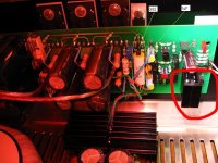
But I still can't figure out what's the black thing enclosing D1, Q18 and Q21. Is it some sort of heatsink? 😀
Last edited:
heatshrink tube , nothing else
No, I mean this black thing circled in red. 😀
Attachments
Have you looked at the PCB layout?
What is located where those black mysteries reside?
A pair of To126 transistors.
Does that give you a clue rather than reading.
What is located where those black mysteries reside?
A pair of To126 transistors.
Does that give you a clue rather than reading.
Have you looked at the PCB layout?
What is located where those black mysteries reside?
A pair of To126 transistors.
Does that give you a clue rather than reading.
You better look at the picture more carefully. Are the 2SC3423's that huge?
Now, I have to ask a stoopid question: what is the purpose of heatshrinking together a LED and a single transistor?
look at the datasheet. It tells you that 2sc3423 are To126.Are the 2SC3423's that huge?
look at the datasheet. It tells you that 2sc3423 are To126.
I have partially populated PCBs, and you don't have to tell me that 2SC3423's are TO126. I'm using those that I bought in the 1990's.
No, I mean this black thing circled in red. 😀
It does look like four transistors in a hug with heatsink.
is there anybody out there that reads the thread and what Roender has to tell us?
I did read it once few months back, but due to the noise posts like this, it's kinda difficult to trace back what you need

No, I mean this black thing circled in red. 😀
Just there to thermally couple the transistors and the diode. It's a refinement more than a necessity, as they are touching anyway. The thermal time constants are fairly large compared to music signals, so they just keep bias drift lower. You can use heatshrink tubing there, as the total dissipation is low.
Sheldon
- Home
- Amplifiers
- Solid State
- RMI-FC100, a single stage audio power amplifier