We do not often see BC368 BC369 used.
These are High Current 2000 mA TO-92 transistors.
The limitation is Max 20 Volt Collector-Emitter voltage.
But for preamp / headphone amplifiers these can be a very good option.
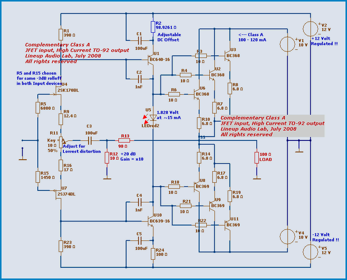
My example here is a Complementary Class A preamp, with 2SK170 / 2SJ74 input.
I use dual +-10 Volt (=20 Volt) for output stage. And a bit higher for Input/Vas.
For being a preamp, this one is POWERFUL and very low distortion.
Can drive Headphones, for example 32 ohm, with vanishing low distortion.
( Below -100dB, some 2nd order harmonics )
Notice. Important!!!
If you attach Headphones, be sure to use an Output Capacitor
Until you are absolute sure the DC- Offset is stable.
Because this amplifier has got not DC global feedback.
The AC global feedback is coupled with C3 = 100 uF to input JFET stage.
Enjoy 🙂
Lineup
These are High Current 2000 mA TO-92 transistors.
The limitation is Max 20 Volt Collector-Emitter voltage.
But for preamp / headphone amplifiers these can be a very good option.
My example here is a Complementary Class A preamp, with 2SK170 / 2SJ74 input.
I use dual +-10 Volt (=20 Volt) for output stage. And a bit higher for Input/Vas.
For being a preamp, this one is POWERFUL and very low distortion.
Can drive Headphones, for example 32 ohm, with vanishing low distortion.
( Below -100dB, some 2nd order harmonics )
Notice. Important!!!
If you attach Headphones, be sure to use an Output Capacitor
Until you are absolute sure the DC- Offset is stable.
Because this amplifier has got not DC global feedback.
The AC global feedback is coupled with C3 = 100 uF to input JFET stage.
Enjoy 🙂
Lineup
Attachments

thanks for sharing.
how is the distortion across frequency?
1nF for miller cap lag compensation seems rather large ...
😕
mlloyd1
how is the distortion across frequency?
1nF for miller cap lag compensation seems rather large ...
😕
mlloyd1
Hi.
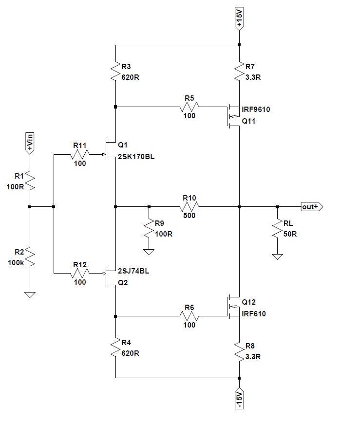
Revision 2.
Gain is now 5.
It is enough for a preamp. Mostly.
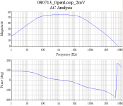
OpenLoop Gain in now lowered to ~ 500.
This gives a feedback factor of x100 ( 40 dB feedback ).
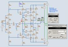
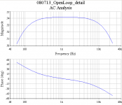
I post here 3 diagrams from my OpenLoop test.
This first shows the setup schematic.
2 mV RMS in.
LOAD is 100 Ohm.
Which actually means ~ 50 Ohm load
as the feedback divider ( R15, R14 ) is 82 + 20.11 = 102.11 Ohm
At OpenLoop Gain x512, THD is 0.153%
Lineup
Revision 2.
Gain is now 5.
It is enough for a preamp. Mostly.
OpenLoop Gain in now lowered to ~ 500.
This gives a feedback factor of x100 ( 40 dB feedback ).
I post here 3 diagrams from my OpenLoop test.
This first shows the setup schematic.
2 mV RMS in.
LOAD is 100 Ohm.
Which actually means ~ 50 Ohm load
as the feedback divider ( R15, R14 ) is 82 + 20.11 = 102.11 Ohm
At OpenLoop Gain x512, THD is 0.153%
Lineup
Attachments
mlloyd1 said:
how is the distortion across frequency?
1nF for miller cap lag compensation seems rather large ...
Distortion vs. frequency?
I have only run 1 kHz. So do not know yet from higher freq.
I will do an oscilloscope run, to see the waveform.
Will be very interesting 😉
Because this amplifier sure is another piece of cake than other preamps.
Very different
Regarding disortion against vs. LOAD.
LOAD has not much effect. (except for loads lower than say 32 Ohm)
Comes from the fact that current feedback is 100 Ohm load, already.
Feedback rail in parallel with 100 Ohm load,
gives a normal nominal load of 50 Ohm.
Which is a good value to use, for this VERY POWERFUL preamplifier.
😎 😎
Say for loads higher than 1k .. we can not expect to notice any change in behavior at all.
Whatever parameter .... !!!!
----------------------
You ask: 1 nF a bit high for compensation?
Well, I use not BC550C or lightweight TO-92 for VAS drivers.
BC639/640 are like BD139/140 in electrical quality.
And that value is on the safe side and also what gives best performance in my Sim.
In real life we may try with more or less, but in this sim-version
we use 1 nF.
Besides, a nice rolloff, reasonable close to audio band ( 20 kHz )
is something I often do.
Say 200-250 kHz.
I do not design Audio amps for RF performancy.
I leave this to others 😀
Hi lineup
Very nice pre-amp design.
What do you think if BC368/369 substituted by 2N4401/4403?
BC368/369 is no longer available from RS & Farnell. I have plenty of 2N4401/4403.
Very nice pre-amp design.
What do you think if BC368/369 substituted by 2N4401/4403?
BC368/369 is no longer available from RS & Farnell. I have plenty of 2N4401/4403.
2N4401 / 2N4403
and maybe 3 paralleled pair in the output of those
hmmmm...
The only thing that is needed, is that output transistors
should work fast and well & with good gain at:
- 10 Volt Collector-Emitter
- 33-50 mA Collector Current (for an idle Class A in output of 100-150 mA total)
This means upto 500mWatt heat. ( 10 V x 50 mA )
What I will do HKC, my HongKong friend,
is to read the 2N4401 and 2N4403 datasheet
and also try to find Spice Models for 2N4401/4403.
Then we will se. If they can come close to BC368/BC369 in performance.
Remember!!! 😎
BC368 and BC369 are special transistors for very high currents operation.
They are small signal ( TO-92 ) rated MAX 2000 mA
Compare for example MAX DC Current, Average Current:
=================================
BC368/369 = 2000 mA
BC550/560 = 100 mA
2N5551/5401 = 300 mA
BC639/640 = 1000 mA
BD139/140 = 1500 mA ( TO-126 Power driver!! )
=================================
I have no problem with buying BC368 BC369
And they are available here in Europe.
see for example
http://www.dalbani.co.uk/catalogue/product_details.php?id=10005
http://www.dalbani.co.uk/catalogue/product_details.php?id=10006
if buying 10 pieces
from http://www.dalbani.co.uk/
they are not expensive at all:
BC368
£0.10
US $ 0.20
Euro 0.15
BC369
£0.10
US $ 0.20
Euro 0.15
in revision 2, i see you've changed to 150pF instead.
that seems more reasonable to me.
mlloyd1
that seems more reasonable to me.
mlloyd1
lineup said:...
You ask: 1 nF a bit high for compensation?
...
I do not design Audio amps for RF performancy.
...
hi
Also I tried with different number of pairs BC368/369 in parallel output
For an idle total output current = 120 mA
Using 4 pairs, was no better performance than using 3 pairs.
Using 2 pairs makes these TO-92 a little bit hot. ( 600 mW continious )
Conclusion:
3 pairs is a safe operation
3 pairs is better than 4 regarding performance
3 pairs is optimal for this situation
yes, mlloyd1
But that schematic 'new version' was the setup of
my OPEN LOOP = no feedback, testing
which is stated in my post
What I use in the CLOSED LOOP of new version
I have to check out.
But maybe I used 150 pF for closed loop, too
Regards
But that schematic 'new version' was the setup of
my OPEN LOOP = no feedback, testing
which is stated in my post
What I use in the CLOSED LOOP of new version
I have to check out.
But maybe I used 150 pF for closed loop, too
Regards
using
such different Gate Stoppers values for NFET vs. PFET
may seem a bit crazy to some 😀
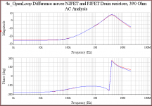
This graph is very interesting.
Blue = 2SK170BL
Red = 2SJ74 BL
As you see, image shows the AC Voltage/Phase angle
across those two 390 Ohm Drain resistors.
Schematic used:
http://www.diyaudio.com/forums/attachment.php?s=&postid=1560865&stamp=1215949714
such different Gate Stoppers values for NFET vs. PFET
may seem a bit crazy to some 😀
I use 1800 Ohm for 2SK170BL
I use 0360 Ohm for 2SJ74BL
(they work both in like 6 mA )
But this quota, 5:1
It made the input transistors share the work perfectly.
Close to perfectly 😎
The resulting open loop AC Analysis done by Lineup Audio Labs shows this very well.
See attached graph.
This graph is very interesting.
Blue = 2SK170BL
Red = 2SJ74 BL
As you see, image shows the AC Voltage/Phase angle
across those two 390 Ohm Drain resistors.
Schematic used:
http://www.diyaudio.com/forums/attachment.php?s=&postid=1560865&stamp=1215949714
Attachments
Hi lineup
If it does not sound much different I still prefer to use 2N4401/4403 even though the price of BC368/369 is not expensive but the freight will cost some money shipping from Europe to Hong Kong just for couple 10 transistors.
Best Regards
If it does not sound much different I still prefer to use 2N4401/4403 even though the price of BC368/369 is not expensive but the freight will cost some money shipping from Europe to Hong Kong just for couple 10 transistors.
Best Regards
anybody
has any comments to my interesting
AC Analyse .. across JFET drain resistors!
http://www.diyaudio.com/forums/attachment.php?s=&postid=1572579&stamp=1217343696
regars
has any comments to my interesting
AC Analyse .. across JFET drain resistors!
http://www.diyaudio.com/forums/attachment.php?s=&postid=1572579&stamp=1217343696
regars
i guess you do not even know
what i am talking about
and do not bother to trim you 'complementary' JFET input stages
yet, i know several using 2SK170 + 2SJ74 for input stage
without considering one tiny bit
they are in fact 2 different devices!!!!
with different data of important parameters for audio
what i am talking about
and do not bother to trim you 'complementary' JFET input stages
yet, i know several using 2SK170 + 2SJ74 for input stage
without considering one tiny bit
they are in fact 2 different devices!!!!
with different data of important parameters for audio
PCB Require
I got a request for PCB.
Thanks for ask, but I do not do those.
Now, this little symmetrical amplifier should not be difficult to PCB.
Or you can hardwire it at a experiment card.
/Regards, Lineup 🙂
I got a request for PCB.
Thanks for ask, but I do not do those.
Now, this little symmetrical amplifier should not be difficult to PCB.
Or you can hardwire it at a experiment card.
/Regards, Lineup 🙂
thank you
[/QUOTE]
Hi Lineup!
Thanks for sharing!
Love n-gnfb projects,
looking to see more ideas from you!
anybody
has any comments to my interesting
AC Analyse .. across JFET drain resistors!
http://www.diyaudio.com/forums/attachment.php?s=&postid=1572579&stamp=1217343696
regars
Nice design Lineup. I just built F5 headamp with 2SK170/SJ74 on inputs driving IRF610/9610 MOSFETs directly. It sounds very good. Great to know there is a TO-92 with 2amp capability. How is heat sinking even able to remove heat from such a tiny TO-92 body? Is three pairs of outputs used to reduce heat dissipation in each transistor?
Here is F5 HA:
Last edited:
- Status
- Not open for further replies.
- Home
- Amplifiers
- Solid State
- Complementary Class A Preamp using BC368-369