Hi,
I have built recently one channel of MF Citation 12 (quasi complementary version) and it sounds great.
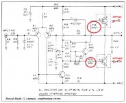
I want to build now the complementary version using IRFP240/IRFP9240 pair. I have seen on many posts overhere that it is recommended to put a 240R resistor on this type of Mosfet. Refering to Mr. Nelson Pass original schematic (see attached pisture) must I change R18 & R19 from 680R to 240R?
Thanks for your help,
I have built recently one channel of MF Citation 12 (quasi complementary version) and it sounds great.
I want to build now the complementary version using IRFP240/IRFP9240 pair. I have seen on many posts overhere that it is recommended to put a 240R resistor on this type of Mosfet. Refering to Mr. Nelson Pass original schematic (see attached pisture) must I change R18 & R19 from 680R to 240R?
Thanks for your help,
Attachments
It will definitely sound better with the smaller resistor.Refering to Mr. Nelson Pass original schematic (see attached pisture) must I change R18 & R19 from 680R to 240R?
Thanks for your help,
If you have a scope you could try even lower.
You could probably try as low as 100 ohms.
The resistors should be as close to the gate as possible (eg soldered directly to it).
Last edited:
Will the amp oscillate with lower gate resistance value?
Thanks for your reply.
PS: Thanh1973 please see your PM.
Thanks for your reply.
PS: Thanh1973 please see your PM.
Maybe. Not much reason to go below 100 ohms, though.
BTW, you actually don't have to get fancy with placing the
Gate resistors right on the Gate. I have gone a couple
feet on occasion without issues.
😎
BTW, you actually don't have to get fancy with placing the
Gate resistors right on the Gate. I have gone a couple
feet on occasion without issues.
😎
Hi NP,
I am completly "stoned" by the sound produced by this simple, rugged, 7-transistors design. It works like a charm at the first power up. I will try with lower Gate resistance values.
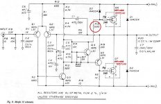
In the quasi complementary version I have implemented Gate resistors in the Gate of IRFP240 (see picture attached).
My question: Must I short R18 or leave it like this?
Thanks for your help,
I am completly "stoned" by the sound produced by this simple, rugged, 7-transistors design. It works like a charm at the first power up. I will try with lower Gate resistance values.
In the quasi complementary version I have implemented Gate resistors in the Gate of IRFP240 (see picture attached).
My question: Must I short R18 or leave it like this?
Thanks for your help,
Attachments
BTW, you actually don't have to get fancy with placing the
Gate resistors right on the Gate. I have gone a couple
feet on occasion without issues.
😎
That is good to know.
Yes Tekko go on.
OK Thanh I will report back after completing and listening to the complementary version. Be patient it can be very quick or it can take time 😱
No answer for my question in post #5?😕
OK Thanh I will report back after completing and listening to the complementary version. Be patient it can be very quick or it can take time 😱
No answer for my question in post #5?😕
I'm not nelson passut it looks like you can remove it since you added the other resistor to the left of the mosfet symbol.
Yes Tekko go on.
OK Thanh I will report back after completing and listening to the complementary version. Be patient it can be very quick or it can take time 😱
No answer for my question in post #5?😕
No rush. I am a very patient person.
Regarding post 5. I would wait for Nelson on that one.
I found it interesting that the Nelson's quasi version has only the one gate resistor but the complimentary version has two gate resistors.
Could you explain that one Nelson?
Pull that 680 Ohm resistor out and replace it with the smaller valued one.
I would leave it in the same position.
Hopefully Nelson can explain the reason why the other mosfet does not have a gate resistor in his circuit diagram.
Just one other comment.
In the article Nelson recommends 100mA bias.
I would be tempted to increase that to around 300mA to 400mA as long as you have the necessary heatsinking.
Hopefully Nelson can comment about the stability of biasing at higher levels.
In the article Nelson recommends 100mA bias.
I would be tempted to increase that to around 300mA to 400mA as long as you have the necessary heatsinking.
Hopefully Nelson can comment about the stability of biasing at higher levels.
My question: Must I short R18 or leave it like this?
R18 prevents the diode from completely dumping the voltage
across the bias capacitor. If you want to remove it, you can
think about removing the diode as well.
😎
Hi Nelson,
From your paper D1 is there to make clipping more symmetrical. If I remove it and in the same time make R18 = 0R there will be no blue smoke coming from my circuit right?😱
I had also the idea to make R18 = 120R, Rg = 120R (to have 240R in the gate circuit of the IRFP240) and keep D1 in its position. Is this mid-way solution better ?
Thanks for your info
- Status
- Not open for further replies.
- Home
- Amplifiers
- Pass Labs
- MF Citation12 - MF gate resistor value