Ripple current rating doesn't effect the values, but if you are running close to the maximum for a given cap then choosing one that is higher will give significantly longer life... but you won't be anywhere near that with this design and values.
Good to know, thanks! 🙂
I think I'm settled now with C12/C18 = 3400uF. Next I want to experiment with the following values for C14/C17:
1240uF
1560uF
2000uF
Just on theory, which of these do you think is best and why? I remember you mentioned 2200uF gives low impedance at line frequency and is a sensible size and you wouldn't go over 2200uF. It would be interesting to know if values lower than 2200uF will also be good. I don't have a 2200uF available to test, but the 2000uF (which actually measures 2125uF) is close enough.
Thank you so much for staying with me! Your help is really appreciated! 🙂
C14 and 17 are "in series" with all the current drawn on each rail so their value will effect the DC voltage that appears across C12 and C18.
capacitive reactance Xc is
Xc=1/2*PI*F*C (that's "1 over 2pi etc) so a higher value cap will "drop" less voltage.
There's no power loss in the cap (I and V are 90 degrees out of phase), so they run cold.
Only real practical consideration is if the heatsinking on the regs is marginal, then an extra volt or two at the input can make a big difference to how hot the regs get.
So you will have to try it and see 🙂
C14 and 17 are "in series" with all the current drawn on each rail so their value will effect the DC voltage that appears across C12 and C18.
capacitive reactance Xc is
Xc=1/2*PI*F*C (that's "1 over 2pi etc) so a higher value cap will "drop" less voltage.
Less voltage drop means less ripple so it's a good thing. However, I have just found that 2000uF for C14/C17 is giving me weird results in RMAA: There is an imbalance in the loopback test for stereo pair channels 7 and 8. Channel 7 has significantly less output level and more THD than channel 8. I wonder if this has anything to do with the 2000uF value, because I'm not getting this weirdness when I use 1560uF for C14/C17. I'll try 1240uF next.
There's no power loss in the cap (I and V are 90 degrees out of phase), so they run cold.
I remember you said that C14 and C17 are the highest stressed caps in this circuit. Why is that so? And despite their being highly stressed, they still run cold?
Only real practical consideration is if the heatsinking on the regs is marginal, then an extra volt or two at the input can make a big difference to how hot the regs get.
So you will have to try it and see 🙂
Yeah, that's the compromise. You get less ripple but more heat on the regs with higher values of C14/C17. But my regs are running cool now. It's now the resistors (that I added to reduce the input voltage to the regs) that are getting hot, but I installed them with very long leads to place them outside the edge of the board and keep their heat away from the board. My heat problem has been licked. 😉
BTW, I calculated a minimum 1 watt required for those resistors but I used 3 watts (they are metal film power resistors). The resistors are so hot that you can't touch them for more than one second. Is 3 watts gonna be fine? What happens if a resistor fails due to extreme heat? Will it become shorted and have zero resistance?
Thanks! 🙂
Last edited:
Can't see any reason why C14/17 would affect measured performance. If that is genuinely so then something is happening that you haven't spotted. If all the rails are correct and the ripple/noise/voltage on the reg outputs is unchanged when you change caps then some other mechanism is at work. Does the 9vac from the tranny feed anything else.
The two caps are highly stressed because they pass all the current to the circuit but they run cold because caps dissipate no power due to the current being 90 degrees out of phase with the applied voltage.
Real caps come close to this ideal... but as they age... as they are run under "high stress" conditions such as this then they deteriorate, the losses increase, ultimately the cap fails. So it's important to use good quality parts... that said your currents here aren't exactly huge 🙂
If the wattage is of the resistors is OK in relation to the actual power dissipated then they will be fine, and resistors usually fail by either going high in value or simply failing open circuit.
Can't see any reason why C14/17 would affect measured performance. If that is genuinely so then something is happening that you haven't spotted. If all the rails are correct and the ripple/noise/voltage on the reg outputs is unchanged when you change caps then some other mechanism is at work. Does the 9vac from the tranny feed anything else.
No, it doesn't feed anything else.
Is it also possible that the caps I used for the 2000uF have too low ESR that resonances are not being dampened and thus the resonances are getting into the circuits being powered?
The two caps are highly stressed because they pass all the current to the circuit
These caps need to have a high ripple current rating then, right?
Won't be anything like ESR being to low or high... if it's a real effect then it's measurable on the output of the regs, either as some strange increase in noise/oscillation or as a drop in the output of one or more of the rails.
Higher ripple current rating usually means a "better" cap and one that will last longer when used in these conditions.
Higher ripple current rating usually means a "better" cap and one that will last longer when used in these conditions.
Won't be anything like ESR being to low or high... if it's a real effect then it's measurable on the output of the regs, either as some strange increase in noise/oscillation or as a drop in the output of one or more of the rails.
The difficulty with my testing is that there are so many wires (the wires I soldered to the reg pins and capacitors for testing because the board is inaccessible). A change in the position or routing of a wire or pair of wires causes a slight change in the output ripple measurement on the regs. When testing the different capacitor options, I have to be consistent throughout all the tests as far as wire routing is concerned. Moreover, one major thing I noticed is that, when all the loopback cables are installed on all channels, the output ripple measurement on the regs is high (for example, 9mV on U6). When I remove the loopback cables and leave only the ones on channels 3 and 4 plugged in, the ripple measurement becomes slightly lower (7.5mV on U6). Then, strangely, when I plug in a pair of cables on outputs 1 and 2 that connect to my NAD receiver, the ripple measurement goes down a lot (3.3mV on U6)! The RMAA tests also confirm this, showing a big improvement in the THD+Noise graph.
I have finished testing the different capacitor options for C14/C17. I found that as long as I'm consistent with the wire routing and the cables installed, there is very little difference in the final output ripple measurement on the regs. Slight differences I found, such as 3.3mV vs 3.7mV, may very well be due to little, unavoidable variations in the test environment (like, how clean the mains power was during the time of testing), so I don't think they're significant and conclusive enough to be relied upon. Therefore, I have arbitrarily chosen 1560uF as my sweet spot. 2000uF is also good but I would like to reduce the heat a little, and I feel that 1560uF is just where I want it to be. 🙂
Please let me know what you think of my analysis. 🙂 Thanks!
Last edited:
When measuring such small values wiring and layout is everything.
If you use a scope probe then clip the probe tip to the probe ground lead... which should give zero noise of course and the finest possible scope trace. Now keeping those shorted, touch the probe tip on the grounds of the PSU etc. Does the trace thicken or show noise ? Make sure you don't short any rails out doing this as the scope is (should be) grounded at the mains.
If it does show noise I have no answer for you... it just highlights the problems of making such small detailed measurements. Every detail has to be attended to eliminate that noise, which is often as much an artifact of the measurement procedure itself as much as being a real issue or problem in many cases... but it's way beyond the scope of describing it on a forum.
I think you have done all you can really 🙂
When measuring such small values wiring and layout is everything.
If you use a scope probe then clip the probe tip to the probe ground lead... which should give zero noise of course and the finest possible scope trace. Now keeping those shorted, touch the probe tip on the grounds of the PSU etc. Does the trace thicken or show noise ?
Yes it does. It thickens to about 4mV. BTW, can I touch the shorted probe on anything in the circuit (input, output or whatever else) and not cause any damage? Can I use this method to see the noise on anything, even resistors, capacitors or diodes, or does it work only for ground?
One last question: What do you think of my choice of UF4002 diodes for this circuit? What would have been your preferred choice of diodes for this kind of circuit? Would Schottky MBR1100 have been better?
Thanks! 🙂
That increase in noise is a result of non ideal (or real world 🙂) connection issues... there's noting you can do about it easily. Why I mentioned it was to highlight the fact the readings at this small level can't be trusted 100% and that 4mv you see may "corrupt" measurements.
Only ever try that on conductors that are at the same potential as the scope ground lead... which means ground and nothing else, and only then just to see what the state of play is.
If the scope were earthed via the mains lead and so to the equipment you are working on then touching a rail with the ground lead would place a dead short across the supply... so never try anything like that.
The diodes are fine. In theory the Shottkys are "quieter"... in practice the effect is minimal and swamped out by the other caps and the regulators. It can sometimes be worth adding a small cap and resistor connected in series, of say 0.1uf and 3.3 ohms across the transformer secondary (9 vac winding) to damp any resonance but it's a bit hit and miss without actually knowing if there is a problem in the first place and what the frequency of that "problem" is. Nothing lost in fitting them though.
Only ever try that on conductors that are at the same potential as the scope ground lead... which means ground and nothing else, and only then just to see what the state of play is.
If the scope were earthed via the mains lead and so to the equipment you are working on then touching a rail with the ground lead would place a dead short across the supply... so never try anything like that.
Good that I didn't try it, though I was curious and was tempted to! 😀
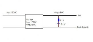
It can sometimes be worth adding a small cap and resistor connected in series, of say 0.1uf and 3.3 ohms across the transformer secondary (9 vac winding) to damp any resonance but it's a bit hit and miss without actually knowing if there is a problem in the first place and what the frequency of that "problem" is. Nothing lost in fitting them though.
Is this something I could do by soldering a resistor and capacitor across the two wires of the wall wart output plug that goes into the power input jack of the Delta 1010? Please see the diagram below and check if it is correct. I have labeled one of the wires as "Red" and the other as "Black" to distinguish the fact that the "Black" one has continuity with the ground pin of the regulators in the 1010. Also, is that the correct order -- "Red" wire to 3.3 Ohm resistor to 0.1 uF capacitor to "Black" wire or should it be reversed? Does the order matter?
I also need more details: How many watts rating should the 3.3 Ohm resistor be, and should it be a metal film power resistor or a wire-wound? And for the 0.1uF capacitor, I have 0.1uF 100VDC X7R ceramic and 0.1uF 63VAC/100VDC metalized polyester film available. Which of these would be better?
Thanks! 🙂
Attachments
That's correct, the order of the parts doesn't matter. The resistor should be an ordinary 0.5 or 1 watt carbon or metal film type, not wirewound as that's inductive. Neither will get the slightest bit warm. Either ceramic as long as it's a decent one or poly, it doesn't matter. Compressed disc ceramics used to fail a lot many years ago... something I have grown with so I am always wary.
Either ceramic as long as it's a decent one or poly, it doesn't matter. Compressed disc ceramics used to fail a lot many years ago... something I have grown with so I am always wary.
I'll use the film then.
If there is resonance, is it a problem with the wall wart or the 1010? I'm wondering if I should do this mod on the 1010 board instead of the wall wart.
BTW, how do you check if there is this resonance and what its frequency is? And how do you calculate the appropriate R and C values to dampen the resonance given its frequency?
Thanks! 🙂
The best checks are with the 'scope to see if the unregulated supply is clean, and if the incoming 9vac is "clean and smooth".
It's hit and miss as I mentioned before because until you identify an actual problem you can't really solve it. Things such as lead length, lead resistance and the inductance of the tranny secondary all come into play, and unless there is an abrubt change in current no ringing would be seen anyway.
So the resistor and cap is a generally accepted method of trying to cover any possible problem by totally damping the winding rather than trying to target a very specific frequency.
It is a real problem though. Once had an Hitachi battery/mains radio that had a harsh buzz on AM. Found that just putting a finger on the bridge reccy stopped the noise and adding a 0.1uf cap across the tranny secondary stopped it dead... it is a common issue.
The best checks are with the 'scope to see if the unregulated supply is clean, and if the incoming 9vac is "clean and smooth".
So it's a problem with the wall wart, not the 1010? Because if so, it makes sense to do the mod on the wall wart wires as I diagrammed so that the wall wart can be used for something else other than the 1010 and not have this problem.
It's hit and miss as I mentioned before because until you identify an actual problem you can't really solve it. Things such as lead length, lead resistance and the inductance of the tranny secondary all come into play
Would it help to replace the cord of the wall wart with a thicker one? It's kinda thin as it is now.
So the resistor and cap is a generally accepted method of trying to cover any possible problem by totally damping the winding rather than trying to target a very specific frequency.
So I could do this mod on any wall wart that's an AC to AC step down transformer? If so, I have lots of wall warts waiting to be modded. 😉
It is a real problem though. Once had an Hitachi battery/mains radio that had a harsh buzz on AM. Found that just putting a finger on the bridge reccy stopped the noise and adding a 0.1uf cap across the tranny secondary stopped it dead... it is a common issue.
Good to know, thanks! 🙂
You can add more than one snubber network, one in the wall wart and one at the other end. You won't change anything trying different cables, although if it's metres long and you don't need that then chop it down a bit. The R/C network just kills the problem instantly anyway... don't worry 🙂
You can add more than one snubber network, one in the wall wart and one at the other end.
You mean another 3.3 Ohm in series with 0.1uF placed in the 1010's board right before the supply goes to the diode bridges? So there are two RC snubbers now - one in the wall wart and one in the 1010's board? Is this gonna work better than just one RC snubber that's placed in the wall wart?
That's it, one at each end.
Is it better ? If it reduces a noise problem then yes... it's not going to make it worse anyway. This is why I keep saying you must measure and see what's going on. If there's no problem to begin with (and there probably isn't) then they will have no noticeable effect anyway.
These kind of issues are unique and different to each application.
I don't have 3.3 Ohm resistors and wanted to buy some but the stores were all closed yesterday - it was Labor Day. I'll try again today.
Meanwhile, I have discovered something very crucial that was quite a revelation. Yesterday, to my puzzlement, suddenly my RMAA tests were showing bad THD graphs. I tried rearranging the wires and cables to see if the problem would go away. Nope, no dice. I even removed all the wires that I had soldered to the regulator pins and capacitors for testing, thinking that they were acting as antennas. Still didn't help.
Finally, I removed the big heat sink that's on the +15V reg U4. Yes!!! The RMAA tests are good again! 🙂 Just to be sure, I put the heat sink back, and the tests went bad again. I removed it, and the tests went good. I did this several times and the result was consistent: The tests were good without the heat sink and bad with the heat sink installed.
I thought the heat sink was acting as an antenna because it was big and tall (it is shaped like a tree). So I tried putting just the screw that attaches the heat sink instead of putting the whole big heat sink on. Incidentally, the screw attaches to the chassis through a screw hole on the chassis underneath the PCB. The design of the 1010 is using the chassis as a heat sink by means of the screw connection. Well, what do I know, even with just the screw attached, the problem persists!
What do I have here? I think it's a ground loop, don't you think so? But I'm wondering why all of a sudden this problem pops up without any change in my system. I still have all the same devices connected and powered on as in the days before (PC, monitor, receiver, headphone amp, scope, and lamp). The only thing that changed was that I added a 0.1uF film cap on the output of all the regs. That couldn't possibly cause a ground loop! Nevertheless, I removed those film caps, tested again, and, as expected, the problem did not go away.
Funny, the bad RMAA THD graphs I was having months ago was what drove me to mod this thing. I thought it was a problem of failing caps due to overheating in the power supply. I replaced the caps and got some temporary relief. But the problem would come back again. And now, it seems, it turns out to be not the caps but a f*****g ground loop problem!
How do I fix this problem? I'm thinking of removing the electrical connection between the heat sink and the chassis screw hole to stop the ground loop. What do you think of removing the screw hole where the heat sink screw attaches to on the chassis? The screw hole is a 3.5mm metal protrusion from the chassis. I can cut it off with a Dremel tool. Then I can install the heat sink screw with a nut underneath the board, making sure that the nut does not directly touch the chassis by putting an insulator between the nut and the chassis. Ideally, this insulator material should have zero electrical conductivity but very good thermal conductivity so that some of the heat can still flow to the chassis. Do you have any suggestions for such a material?
Thanks! 🙂
Last edited:
Can you put insulating kits on the regulators ?
MULTICOMP|MK3306|INSULATING KIT, MICA TO-220 | Farnell United Kingdom
MULTICOMP|MK3306|INSULATING KIT, MICA TO-220 | Farnell United Kingdom
- Status
- Not open for further replies.
- Home
- Amplifiers
- Power Supplies
- Need help on Delta 1010 PSU mods