Folks, I have a 100W Marshall Super tremolo type 1959 built in in 1970 (4 EL34s in the output). The main 4 Amp fuse pops after 1/2 minute and I noticed the EL34 plates glowing. I pulled the output tubes and read only -4VDC on the grid pin 5 of the sockets. I was looking for -35 to -45 VDC. The Fuses did not blow with the output tubes out. I disconnected the power transformer bias winding on the secondary (white and green wires) and read only 8 VAC at the output of the transformer unloaded. Should it be 100 VAC? The B+ voltage is fine at 512VDC so that part of the transformer seems OK. Thanks, Al
Greetings,
Well it sounds like you have a bad bias winding on the transformer. What you could do instead of trying to track down another transformer is to hookup a filament transformer backwards on the present filament line and use the 115 coming out.
Well it sounds like you have a bad bias winding on the transformer. What you could do instead of trying to track down another transformer is to hookup a filament transformer backwards on the present filament line and use the 115 coming out.
Folks, I have a 100W Marshall Super tremolo type 1959 built in in 1970 (4 EL34s in the output). The main 4 Amp fuse pops after 1/2 minute and I noticed the EL34 plates glowing. I pulled the output tubes and read only -4VDC on the grid pin 5 of the sockets. I was looking for -35 to -45 VDC. The Fuses did not blow with the output tubes out. I disconnected the power transformer bias winding on the secondary (white and green wires) and read only 8 VAC at the output of the transformer unloaded. Should it be 100 VAC? The B+ voltage is fine at 512VDC so that part of the transformer seems OK. Thanks, Al
Folks, I have a 100W Marshall Super tremolo type 1959 built in in 1970 (4 EL34s in the output). The main 4 Amp fuse pops after 1/2 minute and I noticed the EL34 plates glowing. I pulled the output tubes and read only -4VDC on the grid pin 5 of the sockets. I was looking for -35 to -45 VDC. The Fuses did not blow with the output tubes out. I disconnected the power transformer bias winding on the secondary (white and green wires) and read only 8 VAC at the output of the transformer unloaded. Should it be 100 VAC? The B+ voltage is fine at 512VDC so that part of the transformer seems OK. Thanks, Al
Yes, you could disconnect the bais winding and then use a tiny heater transformer but your amp is valuable enough that you might want the spend some money and replace the power transformer.
The other way to go is to make a small 1/2 wave -100 suply from a diode and 1/2 of the B+ secondary. This gives you twice as many volts as you need but you drop them with a 100V zenier
The thing that would bother me is knowing there must be a shorted turn some place or why the low voltage? A new PT might cost $100
I think the bias voltage on a 100 Watt Marshall is close to 90VAC right off the xfmr so it looks like the bias winding is fried. Check the rest of the bias circuit for shorts to ground. Possibly one of the 8UF/150V electrolytics is bad.
Craig
Craig
I agree with the other posters its most certainly the bias I ahd a similar problem on a laney 50watt amp but unfortunately in my case the previous owner had decided to change the 0.5 amp fuse for a 3 amp one and the mains transformer went on fire
On the laney the bias is derived from one half of the 350 + 350 windings via a diode so you dont actually need a dedicated winding for bias ( valves in this type of situation consume no grid current so you could actually use dry batteries and they would last for years ) my only reservation would be if you are really sure the voltage on the transformer is low then it might be open cuircuit ( safe enough ) or shorted windings ( potential fire hazzard )
On the laney the bias is derived from one half of the 350 + 350 windings via a diode so you dont actually need a dedicated winding for bias ( valves in this type of situation consume no grid current so you could actually use dry batteries and they would last for years ) my only reservation would be if you are really sure the voltage on the transformer is low then it might be open cuircuit ( safe enough ) or shorted windings ( potential fire hazzard )
Hi there,
I would check the coupling caps on the outputs of the phase splitter .022uf I think on your amp. If these got leaky after time HT voltage from the anodes of the phase splitter leaks to the grids of the power tubes lowering the negative bias voltage.
Mario.
I would check the coupling caps on the outputs of the phase splitter .022uf I think on your amp. If these got leaky after time HT voltage from the anodes of the phase splitter leaks to the grids of the power tubes lowering the negative bias voltage.
Mario.
Keep in mid that this power transformer secondary uses a VOLTAGE DOUBLER arrangement for the B+ .... So your Center-Tap is not at ground potential...
The bias winding is very tiny wire..too small actually...
WHen you apply exactly 120V at the primary leads with 160mA overall current draw across the High Tension fuse holder you will get a B+ of 500V ....provided caps are in good shape... The BIAS winding is exactly at 100V at that point....
If your BIAS winding was shorted the transformer would HUM and produce a burning smell... If it is open, it can be fixed...I have fixed many of these T2562 power transformer bias windings without rewinding them..from going in from the side of the paper...
This BIAS winding has a WHITE and GREEN wire....I would make sure you have the correct green wire...since there are two green wires on this transformer going to ground...
Chris
I have the Bugera 1960, clone of Marshall 1959 SLP. 4xEL34 etc etc....
I notice a little screen glow too, but sounds terrible with bias adjust
such that screen glow completely goes away.
Fixed bias should be -40V to -50V depending the tube? I guess you
would have to measure idle cathode current to know for sure. else
observe the screen in a dark room while playing full blast...
How much glow is allowed? I'm sure we never want screen brighter
than cathode. But is even that much considered way too much?
I'm not talking the blue glow, I'm talking the dark shadow of screen
wire disappears, dim orange merged into the glow of the cathode...
Is that taking it too far, or just right?
Last edited:
Suspect possible mods to the bias circuit
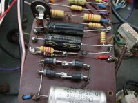
Thanks to everyone for the responses to my question – very helpful. I will need to replace the power transformer with a new one since the bias winding is bad on the original. Would a Hammond 290HX be a good choice? Also, I noticed something strange about the bias circuit in this amp that could be related to the bad winding…. The original input resistor (22K) has been paralleled with a 47K resistor and also the 2 x 8uf caps (per the schematic) are now 100uf/100V caps. Does this appear to be an attempt to jack up the bias voltage to compensate for a failing bias winding at some point in the past? I'd think those 100ufs would put quite a current surge on the bias winding on power-up. I don’t believe this is a factory mod so I plan to remove the 47K resistor and replace the 100uf caps with 8uf/160v caps when I replace the PT. I've attached a schamatic and a jpg of the circuit. Thanks for your help.... Al
Thanks to everyone for the responses to my question – very helpful. I will need to replace the power transformer with a new one since the bias winding is bad on the original. Would a Hammond 290HX be a good choice? Also, I noticed something strange about the bias circuit in this amp that could be related to the bad winding…. The original input resistor (22K) has been paralleled with a 47K resistor and also the 2 x 8uf caps (per the schematic) are now 100uf/100V caps. Does this appear to be an attempt to jack up the bias voltage to compensate for a failing bias winding at some point in the past? I'd think those 100ufs would put quite a current surge on the bias winding on power-up. I don’t believe this is a factory mod so I plan to remove the 47K resistor and replace the 100uf caps with 8uf/160v caps when I replace the PT. I've attached a schamatic and a jpg of the circuit. Thanks for your help.... Al
Attachments
Don't blame the transformer. The problem could be the bias rectifier or other component in that circuit.
The tiny 8uf caps were replaced by someone to clean up the bias supply. Ripple on the bias will come out the speaker as hum. And changing the resistance in the circuit was done at some point to alter the range of the bias adjustment. These are common things to see.
yes, that Hammond 290HX ought to work, AES sells it listed as a 100w JCM Marshall replacement.
yes, that Hammond 290HX ought to work, AES sells it listed as a 100w JCM Marshall replacement.
The solution
Folks, First of all thanks for all the great help. I replaced the power transformer with a Hammond 290HX and it's fixed. I also changed the 2 filter caps in the bias PS from the modded 100Uf back to 8uf. Thinking that the initial surge into the 100ufs may have popped the bias winding of the xfmr after a few cycles of operation. Thanks again all. Al
Folks, First of all thanks for all the great help. I replaced the power transformer with a Hammond 290HX and it's fixed. I also changed the 2 filter caps in the bias PS from the modded 100Uf back to 8uf. Thinking that the initial surge into the 100ufs may have popped the bias winding of the xfmr after a few cycles of operation. Thanks again all. Al
- Status
- Not open for further replies.
- Home
- Live Sound
- Instruments and Amps
- Marshall 1959 (Super Tremolo) repair help