I construction a simple amplifier,none capacitor,feel sound well,someone give me some advice,my english very poor,hope everyone understand,~~haha~~
in fact,i use irf630 instead of irf610

in fact,i use irf630 instead of irf610
Hello.
I use MultiSim, too.
I tested your circuit. It works well.
What I should change.
1. I should use +-18V Supply
2. Use NE5534P. Is a better opamp than NE5532
And you can build two channels separate. Dual Mono blocks.
3. IRF630 is better. 74 Watt. IRF610 only 36 Watt.
Myself, I should go for IRF540N/IRF9540N. More than 100 Watt
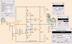
Here is my variant. No longer as simple as your. But it is not very difficult.
It gives max 14 Watt RMS into 8 Ohm
By using 2 BOOTSTRAP capacitors we help opamp to give higher volt out.
One thing to fix is the DC offset: -115 mV
This can be done using Pin1 and Pin5 of NE5534
I use MultiSim, too.
I tested your circuit. It works well.
What I should change.
1. I should use +-18V Supply
2. Use NE5534P. Is a better opamp than NE5532
And you can build two channels separate. Dual Mono blocks.
3. IRF630 is better. 74 Watt. IRF610 only 36 Watt.
Myself, I should go for IRF540N/IRF9540N. More than 100 Watt
Here is my variant. No longer as simple as your. But it is not very difficult.
It gives max 14 Watt RMS into 8 Ohm
By using 2 BOOTSTRAP capacitors we help opamp to give higher volt out.
One thing to fix is the DC offset: -115 mV
This can be done using Pin1 and Pin5 of NE5534
Attachments
First thanks your advice,In reality,some little diffefrence to above,in output I add 2 capacitor(1000uf+1000uf) of one channel,protected my speaker,extra advantage is reduce current, i guess bass may be affect
You have to add bias management circuit for the output stage otherwise the circuit will end up in thermal runaway.
I see your circuit,don't understand your 220Ohm,drop it may be better,add to opamp drive current
http://www.diyaudio.com/forums/solid-state/21526-gate-stopper-values.html
220 Ohm at GATE of MOSFET is to prevent oscillation.
They are used very often and we call these resistors Gate Stoppers
You can find them resistors in almost every MOSFET amplifier.
Last edited:
I construction a simple amplifier,none capacitor,feel sound well,someone give me some advice,my english very poor,hope everyone understand,~~haha~~
in fact,i use irf630 instead of irf610
View attachment 185012
Dear LoveVirus,
Why not use the NE5534 instead and drive the output stage from pin 5? Basicly you drive them direct from the NE5534 VAS which will be in class A.
With kind regards,
Bas
It gives max 14 Watt RMS into 8 Ohm
By using 2 BOOTSTRAP capacitors we help opamp to give higher volt out.
One thing to fix is the DC offset: -115 mV
This can be done using Pin1 and Pin5 of NE5534
Dear Lineup,
Doesn't that increase the distortion of the NE5534? I remember some older measurement I made that distortion rise if you go above approx. 50mV, by miss balance the input transistors in the NE5534
With kind regards,
Bas
Watch out for thermal runaway!!!
Insert a bipolar transistor in series with R4/R5 and mount it on the same heatsink.
See how it is done in other schematics with IRF fets.
Insert a bipolar transistor in series with R4/R5 and mount it on the same heatsink.
See how it is done in other schematics with IRF fets.
Because of large loop feedback exist,may be not happened your worried,don't only guess,have a test,I listen half-hour it,not end up in thermal runaway.🙂You have to add bias management circuit for the output stage otherwise the circuit will end up in thermal runaway.
http://www.diyaudio.com/forums/solid-state/21526-gate-stopper-values.html
220 Ohm at GATE of MOSFET is to prevent oscillation.
They are used very often and we call these resistors Gate Stoppers
You can find them resistors in almost every MOSFET amplifier.
Gate Stoppers exist is right,but in this circuit resistor divider can insted of gate stoppers,if you do not believe can test it. I think 220 ohm can reduce drive current.
Dear LoveVirus,
Why not use the NE5534 instead and drive the output stage from pin 5? Basicly you drive them direct from the NE5534 VAS which will be in class A.
With kind regards,
Bas
This circuit is a base test,I not only use ne5532 or ne5534 otherwise AD827,TL082,TL072,LT353 and so on,By my test make a choise of end.
In bbs.hifidy.com I send a similar message,someone tell me resistor divider too big,suggested that I use constant pressure,I think it is not calculate gate current.
Ciss 600pf and Cdss 250pf at 100khz total 0.6ma+0.25ma
600(pf)x(1E-12)x10(v)x100(khz)x(1E+3)=6E-4(A)=0.6mA
250(pf)x(1E-12)x10(v)x100(khz)x(1E+3)=2.5E-4(A)=0.6mA
I dont know this is right or wrong?
Ciss 600pf and Cdss 250pf at 100khz total 0.6ma+0.25ma
600(pf)x(1E-12)x10(v)x100(khz)x(1E+3)=6E-4(A)=0.6mA
250(pf)x(1E-12)x10(v)x100(khz)x(1E+3)=2.5E-4(A)=0.6mA
I dont know this is right or wrong?
At first I don't certainty it work well,output I use OCL,protected my speaker.Watch out for thermal runaway!!!
Insert a bipolar transistor in series with R4/R5 and mount it on the same heatsink.
See how it is done in other schematics with IRF fets.
above is wrong not
250(pf)x(1E-12)x10(v)x100(khz)x(1E+3)=2.5E-4(A)=0.6mA
is
250(pf)x(1E-12)x10(v)x100(khz)x(1E+3)=2.5E-4(A)=0.25mA
Last edited:
If you real test,remember protected your speaker,after all it's a test not a product.Because of large loop feedback exist,may be not happened your worried,don't only guess,have a test,I listen half-hour it,not end up in thermal runaway.🙂
About feedback, why must it take from speaker (MOSFET source) output, rather than from OpAmp output? As I think the MOSFET is in Source Follower/Power Follower (no gain)?
Ervin L
Ervin L
Be sure two mosfet having identical parameterAbout feedback, why must it take from speaker (MOSFET source) output, rather than from OpAmp output? As I think the MOSFET is in Source Follower/Power Follower (no gain)?
Ervin L
You can feedback from OpAmp output
Here is my variant. No longer as simple as your. But it is not very difficult.
Lineup, how will I get 100 watt from +/- 18V supply?
Can we interchange output devices to provide some gain? We can then operate the output stage at higher voltage (say 30V rails) and use zener droppers for the opamp.
Would this work?
- Status
- Not open for further replies.
- Home
- Amplifiers
- Solid State
- simple ne5532 and irf630