Some time ago I built an EL34 PP amp and as we do, tried many mods!🙂
When reading Aspens Tube Amp Book I saw a mod where the EL34s were protected with reverse biased diodes (Across each O/P Tube) to protect them and extend life from the back EMF of the O/P Tx. (Guitar amp mod)!
I tried this mod on the Hifi Amp and the results were much cleaner sound also most of the blue electron cloud (Blue glow) seemed to reduce in the valves. I know this is dependant upon perceived listening tests and we do not like the idea of improving valve sound with semiconductors. Switching noise etc, etc. I let a few HIFI nuts myself included (LOL) listen they thought it was very good! I tried removing the diodes and the sound seemed to be muffled by comparison! Also obviously different types of diode gave different changes! (Soft recovery, Hex, Etc) Hex seemed to give best results at the time!
I assume others have tried this?
Regards
M. Gregg
Aspens mod showed 3 diodes in series I guess to allow for a diode to fail during a stage performance, I just used one hex diode per tube. This was just DIY try it and see! I was surprised at the results!
The diodes stayed on the amp!
I assume this would work with other pp pentode amps although I have not tried it!
The diodes stayed on the amp!
I assume this would work with other pp pentode amps although I have not tried it!
Last edited:
IIRC Bob Carver used this idea too.
I will have a look for a schematic I remember in the past "Carver amps". You don't see many about these days even mentioned in forums.
would you mind showing a small schematic of this mod? I can't seem to put a picture in my mind this slow morning. Thanks.
I will have a look for a schematic I remember in the past "Carver amps". You don't see many about these days even mentioned in forums.
It was in this thread - not 100% they are the same but it did use diodes on the gates I think.
would you mind showing a small schematic of this mod? I can't seem to put a picture in my mind this slow morning. Thanks.
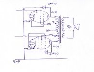
The MOD involves connecting Diodes to the plate connection of each output tube from the plate to ground. That is the connection of the output transformer to the anode of the tube to ground reverse biased so the diode blocks te HT. If you were using a 1N4007 the band would point to the Anode of the tube. You can use BYV96E diodes however HEX are better!
Obviously if you connect them in forward bias they will short your HT to ground! The guitar mod showes 3 1N4007 in series per tube. The type of diode has a big impact on the sound (from a HIFI point of view!)
Here is the schematic!
Attachments
Last edited:
I used that long time ago in guitar amps. There were several KD-213 diodes in strings, since they were only available high frequency power diodes then.
So this might work on an EL84 amp too?
Part number for the best diodes for this?
Interesting....
Fran
Part number for the best diodes for this?
Interesting....
Fran
You need to bear in mind that this is considered a risky mod.
If the diode gets tired and dies it will usually form a short circuit and fry your output transformer, and possibly your power transformer too.
So while an 1N4007 is good in theory I'd be fitting something much better.
If the diode gets tired and dies it will usually form a short circuit and fry your output transformer, and possibly your power transformer too.
So while an 1N4007 is good in theory I'd be fitting something much better.
You need to bear in mind that this is considered a risky mod.
If the diode gets tired and dies it will usually form a short circuit and fry your output transformer, and possibly your power transformer too.
So while an 1N4007 is good in theory I'd be fitting something much better.
If you do not have any fuses on your HT B+ rail then obviously any component failure could cause damage. I have always put a seperate fuse on the HT for left and right channels. If you have a semiconductor rectifier you have two diodes between B+ and ground. You can always get flash over of O/P tubes with high HT so fuses are good for damage limitation! If you do not like the thought of fuses in the B+ (part of the signal path) then just fit a 0.1 polyprop at 1000V across it! It will block DC should the fuse fail and presents a signal path not using the fuse element!
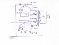
Any way if you want to try it using the way Aspen did it in the Amp Book! Here is the schematic using 3 diodes per tube.🙂
I have tried diodes:
BYV96E, UF5408, 1N4007, Also any fast recovery, soft recovery, Hexfred types of 1000V+ at 1A or more!
Regards
M. Gregg
Attachments
Last edited:
You need to bear in mind that this is considered a risky mod.
If the diode gets tired and dies it will usually form a short circuit and fry your output transformer, and possibly your power transformer too.
So while an 1N4007 is good in theory I'd be fitting something much better.
@ Globulator nice one yes if you attempt this mod it is at your own risk!🙂
Last edited:
As far as I know, that simple protective circuit shouldn't have any audible effects - unless your amp is constantly running at the edge of arcing through the insulations of the output transformer's windings. (e.g. reverse breakdown voltage of three series 1N4007 is about 3 kilovolts) 
Last edited:
As far as I know, that simple protective circuit shouldn't have any audible effects - unless your amp is constantly running at the edge of arcing through the insulations of the output transformer's windings. (e.g. reverse breakdown voltage of three series 1N4007 is about 3 kilovolts)
i guess i am struggling as well to figure out how this could affect sound. or anything for that matter. there should be no movement of electrons through the diodes at all except under bad situations.
I'm with jrenkin. If there is a change in the audio, the diodes are conducting and generating harmonic distortion. Under normal operating conditions, the tube anodes should never go negative.
i guess i am struggling as well to figure out how this could affect sound. or anything for that matter. there should be no movement of electrons through the diodes at all except under bad situations.
O.K so lets look at a standard 12V relay circuit. The relay is in the collector of the transistor, the relay coil has a reverse biased diode across the coil i.e. the diode is connected with its band pointing to the +12v side of the relay. So under normal conditions the diode should never conduct because the 12V supply is never switched off. The transistor switches the relay with no problems.
O.K. now remove the diode the transistor will fail why, because the diode was conducting when the relay switched off? because the relay coil generates it own voltage called back EMF it is independant of the 12V applied to the circuit and in opposite direction of supply. This is standard generator theory when the magnetic field collapses at power off the coil is cut by the field this generates the EMF sometimes at 1000v +. Now think about the O/P Tx when the field changes what will happen? (it is a coil with a field around it)
Regards
M. Gregg
Last edited:
I'm interested in seeing an oscilloscope capture of plate signal showing this kind of flyback under normal operating conditions of the amp.
As far as I know, a generic class AB tube amp isn't a switching design like a relay control.
As far as I know, a generic class AB tube amp isn't a switching design like a relay control.
It is not for normal operating conditions. It is for abnormal operating conditions when speaker is disconnected. I saw many guitar amps that are normal AB amps that were not switching design, but output transformers were damaged.
Exactly. There is no reason why the diodes would have any effect under normal operating conditions. They are there only to reverse conduct when the plate voltage exceeds several kilovolts and in such condition to save the output transformer by causing a short circuit that draws enough current to blow the fuse.
It is not for normal operating conditions. It is for abnormal operating conditions when speaker is disconnected. I saw many guitar amps that are normal AB amps that were not switching design, but output transformers were damaged.
that I understand. I can see that it would be a protective circuit for aberrant signals when something goes wrong.
The original thought presented was that it improved sound during normal operation. That is what I am not clear on.
If it does help, I would like to understand how, since I can't seem to figure that part out. My logic would suggest that circuit protection makes sense but that there would be no effect in normal operation. correct me if I am off base.
- Status
- Not open for further replies.
- Home
- Amplifiers
- Tubes / Valves
- Something I found interesting a while ago!