I finally understand why so many DIYers in Japan are still chasing the obsolete 2SK163/2SJ44 pair.
Patrick
Patrick
John,
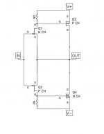
What do you think of this as a power (unity gain) buffer ?
Q1,2 are 2SK170/2SJ74; Q3,4 2SK1530/2SJ201.
Drain resistors ca. 600R, source resistor for Q3,4 say 0R22.
Bias for Q3 ca. 2A. +/- 16V rails.
(I thought it must have been done before, but search and google did not return anything similar with FETs, only with bipolars).
Patrick
Attachments
Last edited:
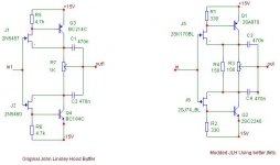
Yes, it is a modified JLH buffer with darlingtons at the output. Try your idea out. Those kind of buffers can be very fast. My version peaks at 16Mhz, slightly. You can get rid of that in many ways. RC filter at the input, bigger gatestopper, ferite bead, coil etc.
Gate stoppers for me.
I don't like ferrite in analogue circuits, and I don't understand magnetism enough to use coils. 😉
Will try some time. Just thought someone might have done this before .....
Gute Nacht,
Patrick
I don't like ferrite in analogue circuits, and I don't understand magnetism enough to use coils. 😉
Will try some time. Just thought someone might have done this before .....
Gute Nacht,
Patrick
I finally understand why so many DIYers in Japan are still chasing the obsolete 2SK163/2SJ44 pair.
So what's the point of using complimentary pairs other than to accommodate unbalanced outputs?
se
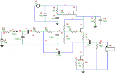
I would recommend that we keep it more simple. We ONLY have 3.5ma per channel and 8.5 V. Use what you have in an optimum way. Also ferrite and lossy ferrite is not optimum for best linearity.
johnloudb, I like your ckt, but maybe 100uH would be better?
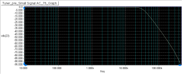
It takes about 200uH, and changing C8 to 0.58u and R10 to 127, to get a sharper response. Now down to -35dB at 100kHz.
I think increasing the Q of the S-K circuit (now 1.5), and some more experimenting with the R10, L1, and C8 could give a sharper slope and maybe reduce the value of L1. I'll see what I can come up with.
So far I've avoided S-plane math and deriving the transfer function and I hope to keep it that way. 🙂
Attachments
Last edited:
john curl said:johnloudb, I like your ckt
Oh yeah, thanks! Nice to hear. The input I got here helped a lot ... I don't have the experience most people here do.
Canceling of second harmonic when you do it right.
Doesn't a differential input give you that already?
se
A diferential input gives 6dB more noise so for a low noise MC Phono i whould not use it.
For MM and up it´s fine and my discrete JOSI Opamp has a differential input.
For MM and up it´s fine and my discrete JOSI Opamp has a differential input.
A diferential input gives 6dB more noise so for a low noise MC Phono i whould not use it.
What about running balanced?
se
What the world needs is a transfomerWhat about running balanced?
se
bassed solution to making the Sony
tuner loose it's ' grain ' 🙂
I think that you are really close, but why the extra regulator?
Oh, Just worried about noise. I guess if it's already quiet enough I won't use it.
- Status
- Not open for further replies.
- Home
- Member Areas
- The Lounge
- John Curl's Blowtorch preamplifier part II