Dear Sasmit,
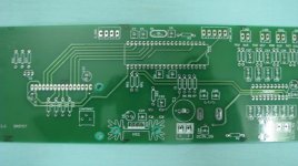
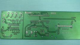
It is an good improvement, and I like the power rails like this. I find the long feedback trace between R4 and R7 a little bit sad. This could be solved by using a 4 layer PCB.
Or by turning R7 90 degrees and shuffling the power lines a bit.
/U.
Or by turning R7 90 degrees and shuffling the power lines a bit.
/U.
But again this would lead to the feedback resistor jumping the power lines.
If you have an extra board fabricated, I might be interested in trying your layout.
I will fabricate some pcb's , but I guess the shipping to US will be pretty expensive.
I added a preamp to my list ..
Attachments
PCB where & How ?
Sasmit
I am also in process of making amp with LM3886 & LM1875, where did you make the professional looking PCBs?
I am interested in making one like them. I am from Goa, India and there are not many PCB manufacturers for DIYs in Goa. If you can help me with the e-mail address I can get in touch with them for my requirement.
Thanks & Regards
Yatin
I will fabricate some pcb's , but I guess the shipping to US will be pretty expensive.
Sasmit
I am also in process of making amp with LM3886 & LM1875, where did you make the professional looking PCBs?
I am interested in making one like them. I am from Goa, India and there are not many PCB manufacturers for DIYs in Goa. If you can help me with the e-mail address I can get in touch with them for my requirement.
Thanks & Regards
Yatin
I am making them from a local guy here in bhubaneswar, I generally use him for ally my microcorntroller dev boards and audio boards etc. He can do double sided PTH but not multilayer . I physically go there and give him the cam files on my thumb drive. I can talk to him if you give me your cam files ( gerber files ).
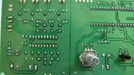
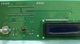
Pcb
Thanks Sasmit for your help !!!!!!!
All my layouts are in eagle (2 for amp & 2 for Power Supply) , is there any way I can convert eagle file in gerber file.
Best Regards
Yatin
I am making them from a local guy here in bhubaneswar, I generally use him for ally my microcorntroller dev boards and audio boards etc. He can do double sided PTH but not multilayer . I physically go there and give him the cam files on my thumb drive. I can talk to him if you give me your cam files ( gerber files ).
Thanks Sasmit for your help !!!!!!!
All my layouts are in eagle (2 for amp & 2 for Power Supply) , is there any way I can convert eagle file in gerber file.
Best Regards
Yatin
look at tangentsoft.net ..for eagle tutorials . The process is very simiple
open a cam job from the menu bar on top of your eagle screen
choose RS274X format -> open the .brd file of the project you would like to generate cam files for.
It will generate 6 files in your project directory
.sts, .sol, .gpi , .drl , .cmp .. I forgot one more. ( just arrange icons by modified and you should be able to see the 6 new files in the folder ).
Before making the cam files be sure to hide whatever layers you do not want to appear in the final board e.g. stop mask or component values ( tvalues , bvalues ) etc.
If you're making boards for the first time in Eagle , I would suggest please check the solder pad sizes for resistors and poly capacitors . These are too small in default packages and will become unsolderable when you make the board. Go to library and edit the package to increase pad sizes .Take a printout of the pdf of your board ( set page scaling to none in print options ) and check track clearance and component fit.
Last edited:
You don't need to edit the packages to increase the pad size in Eagle.
Hit the DRC button in Board view, then go to the Restring tab. Put larger numbers in the Min column for Pads, Top and Bottom. Make sure the DRC still passes for the board fabricator's rules.
Hit the DRC button in Board view, then go to the Restring tab. Put larger numbers in the Min column for Pads, Top and Bottom. Make sure the DRC still passes for the board fabricator's rules.
Last edited:
- Status
- Not open for further replies.
- Home
- Amplifiers
- Chip Amps
- LM4780 paralell pcb