Well, here is the link to the blog, with a practical example using the 6H30P, which is in fact not very different than the 6N6P. If you are interested we can work it out together (let me know the impedance of your headphones!)
Was trying to work out R1 and R2 for a 6N6P for 300ohm headphones in general.
Couldn't get my head around it.
I came up with 136 and 13.6 ohms. Pretty sure this is incorrect.
So splitting the resistors on the cathode is the idea here.
Let me know if you come up with the correct Resistor values lets say for a 6N6P running with 150ohm cathode resistors and 18.5 mA.
I think the Rp for 6N6P is 1800 and mu is 22 no?
Well I tried an estimate with R1 and R2.
I split the 150R with an Allen Bradley 100R for R2 and 50R for R1. Took the output from in between.
Sounding very impressive indeed but I don't have 300R Seins.
I split the 150R with an Allen Bradley 100R for R2 and 50R for R1. Took the output from in between.
Sounding very impressive indeed but I don't have 300R Seins.
back and forth all night and day trying out different combinations and finally decided on one for my headphone design.
SRPP design.
6N6Ps
280v top plate
140v bottom plate
Cathode resistor of top plate split with 100R(Allen Bradley) and 50R (150R in total).
Output taken from in between R1 and R2 leading to a 220uF Nich and 0.47uf Russion PIO bypass cap (I tried all other types finally liking this most).
Bottom tube cathode current set by yellow LED (18mA measured).
Alps 100K pot.
Grid resistors 100R Allen Bradley
PS:
275V AC
HEXFREDS
1uF MKP
1K
200uF
1K
200uF bypassed with MKP10 0.1 uF
😀😀😀😀
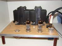
Attachments
Last edited:
Thought I would try a LM317 as a CCS on the bottom tube.
Maybe I got it totally wrong as it sounded awful. airy, distorted and no power.
I measured about 1.22 volts with a 68R resistor on the LM317.
17/18mA should be no? if it's pulling 18mA same as the previous method why is it not working😕
Should it be bypassed with a cap?
Maybe I got it totally wrong as it sounded awful. airy, distorted and no power.
I measured about 1.22 volts with a 68R resistor on the LM317.
17/18mA should be no? if it's pulling 18mA same as the previous method why is it not working😕
Should it be bypassed with a cap?
Last edited:
Thought I would try a LM317 as a CCS on the bottom tube.
Maybe I got it totally wrong as it sounded awful. airy, distorted and no power.
I measured about 1.22 volts with a 68R resistor on the LM317.
17/18mA should be no? if it's pulling 18mA same as the previous method why is it not working😕
Should it be bypassed with a cap?
The LM317 is not recommended as a CCS, look up SY's article (in Articles) for a nice depletion-mode mosfet version.
I'm also not sure an SRPP will like a CCS either, I think they may fight each other and the lower tube's cathode voltage will be all over the place, pumped around by the CCS. Also 1.22 volts is too low for a CCS to work - I think it will need >10V to start behaving well. What was the voltage across the CCS? How much did that leave the SRPP?
Also a CCS bypassed with a cap is no longer a CCS 😉
Just bypassed the LM317 with a 1000uf and it came back to life!!
So it has to be bypassed? I wasn't aware of that.
So it has to be bypassed? I wasn't aware of that.
Also a CCS bypassed with a cap is no longer a CCS 😉
It is CLCC 😀
(Constant Leakage Current Capacitor) 😉
Is that a good thing or bad?🙄
New to me.
Might go back to resistor bypassed because my wife just told me she preferred prototype number #2.
New to me.
Might go back to resistor bypassed because my wife just told me she preferred prototype number #2.
Very strange.
I'm now getting a 20 volt difference at the grid of the top tube.
B+ is 155 and 135 at cathode of top tube. B+ at anode is the same at both.
Measured all resistors and all seem equal. Changed tubes. no diff.
Have to recheck all wiring and resistors again tonight.
😕😕
My wife who loved this version #2 before said it sounded different, "but I haven't changed anything".
She noticed the difference probably due to the current flowing through the tubes affecting the sound on one side.
Before it gave her the goosebumps as it sounded so good.😀
Is that a good thing or bad?🙄
Bad. You want the cathode circuit to be at AC ground (i.e., constant voltage, not constant current).
SY: I went back to cathode resistor bypassed especially as I'm using a SRPP and want the PP to match exactly.
Thxs
😉😉
Thxs
😉😉
SY: I went back to cathode resistor bypassed especially as I'm using a SRPP and want the PP to match exactly.
Thxs
😉😉
Yes I would imagine that would sound better!
Did you try without the bypass capacitor?, I gave up bypass capacitors a while ago and just turn the volume knob up a fraction to compensate.
Now I'm just trying to eliminate some of the remaining caps, or at least bypass them.. ordered some 1uF polys from HK yesterday.
I have also ordered some 6N23P-EV tubes and some 6N1P-EV tubes to try in my SRPP as my PSU is man enough to drive those harder, unlike the 6N6ps that will overstretch it if I bias to 20mA!
I think for a headphone amp however I'd stick with your 6N6ps as they will handle headphones much better. My SRPP only has to drive the gate of a pentode (with an additional 220k bias load) 😉
Was curious.
Would it be advisable to add a CF (bootstrapped) after the SRPP to reduce any distortion on heavy loads (300ohm phones for example).
I tried throwing one together tonight but it needs more work to correct the currents through each and the PS needs adjusting.
Would it be advisable to add a CF (bootstrapped) after the SRPP to reduce any distortion on heavy loads (300ohm phones for example).
I tried throwing one together tonight but it needs more work to correct the currents through each and the PS needs adjusting.
- Status
- Not open for further replies.
- Home
- Amplifiers
- Tubes / Valves
- SRPP - issues understanding how to increase current