Hello
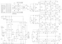
Here is a amplifier schematic , for 2 different type power mosfet or to the new Sanken darlington .
Do someone know more about these ?
Any comment welcome since only the schematic and a couple words ,to me looks like Japanese .
Sorry if already somebody ask about these , I didn't find any info on the forum.
Please take a look .😉
Greetings
Attachments
These are device with integrated diodes for thermal tracking.
They are at least 10 years old.
Elektor did use them in a few designs..
They are at least 10 years old.
Elektor did use them in a few designs..
Hello
Yes the front end I think a bit over complicate but can be still good .
The output section actually very nice .
Probably for a few watt biased in class A or all the way ? 40V PS and 3 pair high power mosfet or darlingtons .
I was curious if anybody tried to clone these . Or the front end to scary?? It seems to me a bit over "the limit" .
Greetings
Well, the front end is probably good thanks to its relative complexity. I´m willing to try simulating it and if I can get it stable in the simulator I might build it and pair it with Cordell´s error correction output stage.
🙂
🙂
Not too complicated at all, cascodes with J-fet CCS's to set the cascode voltages and the current sources for the LTP legs, the VAS mirror is also cascode. The difference in current from the sum of the two LTP leg sources and common mode current source at the bottom for both sides drives the VAS. Quite a neat arrangement I think.🙂
Front end looks like Roender's "RMI" folded cascode. Only difference is the FET CCS for the cascode references. Another neat thing ... it looks like a modular setup , plug in any output stage. #1 is P-N vertical 2- quasi vertical 3 - a mystery?? (proprietary **) 🙂
OS
OS
Last edited:
Maybe if you compare it to a DX. 🙄 It is just a slighty augmented "symasym"... 😎 I might sim it and put it on a 75mm X 75mm PCB module , just for fun (HX "mongrel").Hello
Yes the front end I think a bit over complicate but can be still good .
The output section actually very nice .
Probably for a few watt biased in class A or all the way ? 40V PS and 3 pair high power mosfet or darlingtons .
I was curious if anybody tried to clone these . Or the front end to scary?? It seems to me a bit over "the limit" .
Greetings
OS
Any comment welcome since only the schematic and a couple words ,to me looks like Japanese .
Chinese I think. A couple of points - don't follow the input wiring arrangement shown - decoupling to the input ground (unless you want fairly poor sound). And the output stages have the zobel network on the wrong side of the output choke. According to Doug Self, the zobel is to help suppress VHF parasitics in the output stage, putting it on the far side of an inductor will reduce its effectiveness at that.
Chinese I think. A couple of points - don't follow the input wiring arrangement shown - decoupling to the input ground (unless you want fairly poor sound). And the output stages have the zobel network on the wrong side of the output choke. According to Doug Self, the zobel is to help suppress VHF parasitics in the output stage, putting it on the far side of an inductor will reduce its effectiveness at that.
That is probably a HF input filter (220-470pF) OUR (DIY) zobels are standard ..😀
I don't think this was meant to be built , just an overview of some chinese design with a separate more specific BOM.
OS
Thiele showed two verions of the Network.the output stages have the zobel network on the wrong side of the output choke. According to Doug Self, the zobel is to help suppress VHF parasitics in the output stage, putting it on the far side of an inductor will reduce its effectiveness at that.
One had the Hot to Ground R+C before the Hot to Output L//R coil.
In the other the R+C was often reduced to just a C and placed after the L//R.
Leach uses this version.
Cherry discusses both versions and the infinite set of versions in between.
Where there's a lowish-value resistor in parallel with the choke (considerably lower than the zobel resistor value) then I don't think it matters which side of the choke the zobel goes. Having a non-wirewound resistor in parallel with the choke is a good idea as it provides HF damping.
at least 10 years old.
Wahab,
the SAP15N/P are much older than 10 years, so old that they've become obsolete.
Somewhat expensive those beast..
Anyway, for those who can order at this shop,
i warmly recommend the MN2488/MP1620 Sanken
darlingtons..
Price is honnest considering the perfs of the devices..
Anyway, for those who can order at this shop,
i warmly recommend the MN2488/MP1620 Sanken
darlingtons..
Price is honnest considering the perfs of the devices..
do Sanken publish graphs of Ib vs Ic for various temperatures and Vce for their integrated Darlingtons, similar to what they publish for the discrete devices that they sell?
do Sanken publish graphs of Ib vs Ic for various temperatures and Vce for their integrated Darlingtons, similar to what they publish for the discrete devices that they sell?
http://www.sanken-ele.co.jp/en/prod/semicon/pdf/2sb1648e.pdf
do the two graphs hFE vs Ic qualify the 1688 as linear in any region?
Have Sanken published similar graphs for the two excellent performers that you recommended?
Have Sanken published similar graphs for the two excellent performers that you recommended?
This amplifier is of high class. No doubt about it!
Lot's of good things in the circuit. Especially the input.
But here comes the problems .... to find all 'exotic' transistors used.
The JFETs, NPD5565 and SK373.
The outputs, SK1529/SJ200 or those SANKEN.
My bottomline:
If you use difficult to find transistors/chips in your design
it can not become popular, no matter how good amplifier it is.
Only a few poor chaps will bother to search the world for hard to find devices.
When there are so many other devices that can be found & bought anywhere.
And for much better prices.
- Status
- Not open for further replies.
- Home
- Amplifiers
- Solid State
- A very interesting amplifier schem , do someone knows more about??