I built the following power supply as part of my first tube amp. The with the tubes installed, the power stage B+ measures 315v. A little higher than I was expecting, but that's ok. The real surprise is the B+ for the driver stage is also measuring 315v. The 1.2k 25w dropping resistor isn't providing any voltage drop, and doesn't get warm at all. My ohmmeter verifies that it is 1.2k, so I don't think the resistor is faulty. I've checked my wiring a dozen times and I'm pretty sure it's correct. The only departures from the attached schematic are that I added bleed off (bypass) resisters across the 50uf caps.
What might I be doing wrong?
Jared
What might I be doing wrong?
Jared
Attachments
If there is no load on the output of the 1.2K OHm resistor there will be no current thru it and therefore NO voltage drop. You mentioned something about a bleeder resistor, what size resistor. If there was a 20ma load as on your schematic your voltage drop should be 24V, without a load no voltage drop.
If you have nothing connected to the supply ALL of your voltages will be high.
Craig
If you have nothing connected to the supply ALL of your voltages will be high.
Craig
One other reason your voltages are a bit high is that input capacitor. The image is a bit pixellated on my mobile phone, but it looks like you have a 5U4 rectifier feeding a 100 uf capacitor. That cap needs to be knocked down to about 33 uf or so, or you risk arcing in the rectifier.
If you measure the voltage drop across the dropping resistor, you can work out the actual current drawn by the driver stage. Maybe your 20mA estimate turns out to be way off?
Kenneth
Kenneth
Craig -- The bleed resistors are 1Meg ohm. These voltages were measured with the tubes installed and fully wired except the input tube (6sn7) grids are floating (100k input pot not installed yet). No speakers were connected to the amp. Why would you expect a 24v drop with a 20ma load when PSUD calculates a 120v drop? Is the software not accurate.
Zenith -- Thanks for the cap suggestion. I will adjust it.
Kennith -- My 20ma estimate is for both halves of a 6sn7 @ 180v. Hopefully not too far off.
Zenith -- Thanks for the cap suggestion. I will adjust it.
Kennith -- My 20ma estimate is for both halves of a 6sn7 @ 180v. Hopefully not too far off.
.02 times 1200 equals 24. In your explanation you said nothing about an amplifier only the power supply. The 1 Meg resistors will only provide .3ma of current draw. Are you sure the 1.2K is correct? To get a 120V drop you'll need 100ma of current. If the software program can't do simple math I'd say it's bad.
Try grounding the input grid and see what happens. 20ma might be a tad high. Do you get any voltage across the 1.2K resistor?
Craig
Try grounding the input grid and see what happens. 20ma might be a tad high. Do you get any voltage across the 1.2K resistor?
Craig
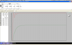
PSUD2 says I2 is drawing 100mA, although the circuit says 20mA. Something wrong there.
In real life, with no grid connections who know what current might be drawn? Usually too much! Are heaters on? No current with heaters on and HT on means something is open circuit.
In real life, with no grid connections who know what current might be drawn? Usually too much! Are heaters on? No current with heaters on and HT on means something is open circuit.
I am currently modifying some old Atma-Sphere MA1s, replacing the 9 pin tubes with four 6SN7s. all four together pull less than 20ma.
Craig
Craig
Ok. There was something glitchy with my PSUD install. I reinstalled it and now I'm getting more reasonable values. Looks like a 6k dropping resistor is what I'll need for a 20ma draw (6000*.02=120v drop). Can someone advise what a 6sn7 will draw at 180v with a 240k plate resistor and a 6.8k cathode load?
Almost nothing, less than half a mA? 240K alone across 180V is only 0.75mA. 6.8K cathode resistor will almost cut off 6SN7. Are you sure these are the right values? I would have guessed an order of magnitude lower!

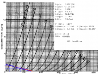
Yes, I am surprised as usually people run 6SN7 with much more current. Anyway, my rough guess of 0.5mA won't be far off. Look at the graph at the bottom of the next page. Your load line goes from 180V on the voltage axis to 0.75mA on the current axis. 0.5mA through 6.8k is 3.4V bias which puts you a bit to the left of the centre of the load line.
Wow. That load line is down there. Thanks for explaining it to me. Now, would you suggest I run the 6sn7 at a greater current or stick with this data sheet setup?
Wow. That load line is down there. Thanks for explaining it to me. Now, would you suggest I run the 6sn7 at a greater current or stick with this data sheet setup?
Depends on what the load is. The 6J5 is basically half of a 6SN7, and I'm using it with an Ipq= 1.0mA here (attached). The linearity is outstanding, and as the output swing is limited, the low Ipq isn't a problem from slew rate considerations.
Your load has to be either a Hi-Z, Lo-C load, or the output needs to be quite limited, otherwise, you will have a slew rate problem at the higher frequencies.
Attachments
I'm not sure if the load in my amp is Hi-Z or Lo-C, but I can tell you the 6sn7 is feeding a 6n6g dual triode via a 511ohm grid resistor. I've never heard of slew rate before. Add it to the list...
I think I'll build it with the low current 6sn7 stage and see how it sounds.
Will report back.
Jared
I think I'll build it with the low current 6sn7 stage and see how it sounds.
Will report back.
Jared
- Status
- Not open for further replies.
- Home
- Amplifiers
- Tubes / Valves
- First Build - PS Voltage Question?