Voltage rating of caps in parallel,
The voltage rating equals the lowest rated cap. Or if both caps identical then the voltage rating stays the same.
example, a 100 volt and 10 volt cap in parallel has a 10 volt rating. Two 63 volt caps in parallel still make up a 63 volt cap.
The capacitance value of parallel caps adds together.
The same voltage appears across each.
I thought that even though the same voltage appears across each cap, the maximum voltage across the caps that they can handle would be greater because of the distribution of the heat to two caps. I thought that the voltage rating is heat related, i.e., more voltage equals more heat. So, for example, if a 10V-rated cap can only take up to 10V because it could not tolerate any more heat than what 10V across it would generate, then two such caps in parallel might be able to handle a higher voltage of, say, 12V across each cap because the heat produced by 12V, though greater than the heat produced by 10V, is spread to two caps. It's like the maximum voltage they could handle has increased. The parallel combination is like a double bigger physical size cap now, and as we know, a bigger size cap has higher voltage rating than a smaller size cap of the same value and series. Doesn't it work that way?
Caps should be run as cool as posible, however modern devices are rated to 105C. Check the markings.
If a cap is too hot and unbearable to touch for 6 seconds, is it something to worry about? I find that C22 and C18 are like this. Is there such a thing as a heat sink for capacitors that I can buy?
Thanks! 🙂
The maximum working voltage is determined by the thickness (or thinness if you prefer) of the dielectric film... it's determined during manufacture with regard to the voltage rating of the cap. It's an absolute 🙂
So for caps in parallel, it's the lowest rating of all the caps so connected.
Too hot to touch ?... definitely something wrong. Is it because the regs run very hot ? and the caps are close.
Also check the polarity is correct... use your meter, make sure the voltage corresponds with the plus and minus markings.
Heatsink for caps... there's no such thing for what we are talking about here.
Caps don't generate heat... as explained regarding the 90 degree phase shift of V and I in AC circuits. Caps across DC (such as reservoir caps) can get warm due to high ripple currents but it would be pretty severe operating conditions to cause tha... certainly more ripple than a loaded 7805 would generate.
If it's heat from the regs causing the issue then you need to move the regs to a heatsink and place the caps further away.
🙂
Before I go... if the caps get hot with no load on the regulators, then you definitely have a construction error/fault.
The regs unloaded will be cold... so will all the caps.
Recheck it all one section at a time.
If the regs are not on heatsinks then they will soon get hot with only a couple of hundred milliamps or so drawn from them.
The regs unloaded will be cold... so will all the caps.
Recheck it all one section at a time.
If the regs are not on heatsinks then they will soon get hot with only a couple of hundred milliamps or so drawn from them.
The maximum working voltage is determined by the thickness (or thinness if you prefer) of the dielectric film... it's determined during manufacture with regard to the voltage rating of the cap. It's an absolute 🙂
So for caps in parallel, it's the lowest rating of all the caps so connected.
Thanks for the heads up on this! 🙂
Too hot to touch ?... definitely something wrong. Is it because the regs run very hot ? and the caps are close.
Also check the polarity is correct... use your meter, make sure the voltage corresponds with the plus and minus markings.
I am sure about the polarity as per the board markings (+ sign indicated on the solder points) but have not checked with a meter. I didn't think I have to because the caps are not exploding and they have been through 14 hours of continuous burn-in already. Wouldn't it take only 15 minutes or so for a cap that is connected in reverse to explode, like what happened to that 100uF cap that I added recently?
I really think that the heat is due to the cramped space, with the caps so close to the regs, plus the fact that the regs are running very hot. I'll post a picture of the PSU section later.
Heatsink for caps... there's no such thing for what we are talking about here.
Is it alright to put a piece of aluminum on the top of a cap? I could cut some pieces from 3mm-thick aluminum that I have.
Caps don't generate heat... as explained regarding the 90 degree phase shift of V and I in AC circuits. Caps across DC (such as reservoir caps) can get warm due to high ripple currents but it would be pretty severe operating conditions to cause tha... certainly more ripple than a loaded 7805 would generate.
If it's heat from the regs causing the issue then you need to move the regs to a heatsink and place the caps further away.
The board is too cramped and it's hard to do that. The only way I can think of is to solder the caps with very long leads so they could be positioned farther away from the regs, maybe outside the edge of the board. But wouldn't that cause an increase in impedance due to the long leads? It's always a compromise. Sigh 🙁
BTW I have another question. If you notice, there is a 1N5818 diode across the output and ground of the +/-15V regs U4 and U5, but the +5V regs U6 and U23 do not have such a diode. Would it be alright to also put an exact same 1N5818 diode across the output and ground of the +5V regs?
Thanks! 🙂
Reverse connected caps probably would explode in seconds or minutes, but... don't take anything for granted... measure them yourself and be sure.
Aluminium on top of the caps... no 🙂
Although the outer can of the cap doesn't connect to the negative lead it's not fully isolated. If you measure on high ohms on a cap case to the leads you may see a reading.
A picture would be interesting !
The diodes are to prevent the possibility of one regulator increasing in output more quickly than the other at start up (due to cap tolerances etc) and reverse biasing the other which can cause the reg to latch in an unpredicatable way.
They are not needed on the 5 volt rails as no reverse bias condition is possible.
Reverse connected caps probably would explode in seconds or minutes, but... don't take anything for granted... measure them yourself and be sure.
Aluminium on top of the caps... no 🙂
Although the outer can of the cap doesn't connect to the negative lead it's not fully isolated. If you measure on high ohms on a cap case to the leads you may see a reading.
A picture would be interesting !
Please see below. That's before I did the mods.
The diodes are to prevent the possibility of one regulator increasing in output more quickly than the other at start up (due to cap tolerances etc) and reverse biasing the other which can cause the reg to latch in an unpredicatable way.
They are not needed on the 5 volt rails as no reverse bias condition is possible.
Just for my education, will putting a 1N5818 diode across the output and ground of the +5V regs do anything bad to the circuit?
Attachments
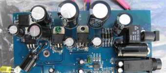
Thanks for the piccy.
A lot of regs in a small space. How hot they get depends on current drawn from each and the voltage differential across each. W=I*V Anything more than a watt or so per regulator is getting too high without heatsinks... particularly with them all together on the PCB
Adding diodes won't do anything bad, but they are not needed.
Thanks for the piccy.
A lot of regs in a small space. How hot they get depends on current drawn from each and the voltage differential across each. W=I*V Anything more than a watt or so per regulator is getting too high without heatsinks... particularly with them all together on the PCB
The resistors that I added to reduce the input voltage going into the regulators are getting hot. I think I should move them outside the edge of the board so they won't radiate the heat they absorb to nearby components. The way I'm going to do that is by soldering them with very long leads, long enough for them to be placed outside of the board. Will that cause any inductance issues or bad side effects?
Adding diodes won't do anything bad, but they are not needed.
Thanks, I was actually thinking of putting the diodes to act like a heat sink (mechanical or electrical, whatever it's going to be) to help absorb the heat. I think anything I can do to reduce the heat, even if it's not going to reduce it a lot, will help. 🙂
I mentioned at the beginning of this thread that my meter was fluctuating wildly when I measured the AC on the input and output of the +15V reg U4. I thought then that only U4 was having this problem, as all the other regs did not manifest this fluctuation when measuring the AC on them. Well, now that I have changed the battery of my meter with a new one (the battery has recently gotten low), I'm seeing that the -15V reg U5 is also having this problem. But the +5V regs U6 and U23 are still fine. So it seems that the low battery condition was giving me a false impression that the -15V was OK. It is actually not OK.
What conclusion can I draw from this? Looking at the schematic, you can see that the large caps C12 and C18 that are used for filtering/smoothing the supply for U4 and U5 are being bypassed by a small 0.1uF cap (this is a ceramic, BTW). After reading this post, I realized that it's actually bad to bypass a large cap with a small one directly/locally on its terminals. Due to trace inductance issues, the small bypass cap should be placed locally on the IC, not on the large filter cap (especially if the large cap is far away from the IC, like 2 cm or farther away).
Therefore, I think that those small bypass caps are the source of my woes on the +/-15V regs. I will try removing them later tonight and see what happens! 🙂
I don't think removing the small caps will achieve anything tbh
You keep saying your measuring AC on the regs... it's DC ! not AC 🙂
If the voltage is a little high on the regs then they will overheat very quickly without heatsinks. Resistors off the board is OK... messy but OK.
What you can try is replacing C19 and C13 with much smaller values of around 10uf. The reasons why are complex, under certain conditions the regs can "start" incorrectly with high capacitive loading close to the output terminal.
I don't think removing the small caps will achieve anything tbh
Yes, you're right, unfortunately. 😱 I just found out it didn't help. I think I'll put them back, but wait, what if I replace them with film? Would film be better than ceramic for that location? I will solder them close to the diodes instead of the filter caps.
You keep saying your measuring AC on the regs... it's DC ! not AC 🙂
I'm measuring both DC and AC. The reason why I'm measuring AC is to see the ripple. Theoretically there should be close to zero AC (very little ripple) on the output of the regs and higher AC on the input. Just now I got 0.003VAC on the output of the two +5V regs and about 0.37VAC on their input. On the -15V reg I got 0.000VAC on the input and 0.012VAC on the output (strange!). On the +15V reg it is fluctuating wildly on both the input and output, I'm unable to get a reading. I think this means there is oscillation on the +15V. Either that, or my meter is fooling me! Maybe I just need a new meter. 😀
If the voltage is a little high on the regs then they will overheat very quickly without heatsinks. Resistors off the board is OK... messy but OK.
Thanks, I will do that then.
What you can try is replacing C19 and C13 with much smaller values of around 10uf. The reasons why are complex, under certain conditions the regs can "start" incorrectly with high capacitive loading close to the output terminal.
Yes, I'll try that.
Going back to my plan of putting a diode across the output and ground of the +5V regs just to act as a heat sink, is a 1N5818 diode OK or should it be something else? (Sorry to ask again, I just want to be sure if the choice of a 1N5818 diode here is fine.)
Thank you so much for helping me! You've been so generous, I really appreciate your help! 🙂
The 1N5818 is fine.
If the readings on the 15 volt reg is weird then consider the possibility that the reg is faulty... it happens.
The sure way to fix something like this is to examine each rail in turn, perhaps running with no load connected.
If the readings on the 15 volt reg is weird then consider the possibility that the reg is faulty... it happens.
The sure way to fix something like this is to examine each rail in turn, perhaps running with no load connected.
If the readings on the 15 volt reg is weird then consider the possibility that the reg is faulty... it happens.
But the DC on the reg is fine (19.83V on the input and 14.87V on the output). It's only the AC that is unstable/unreadable. Could the reg be faulty despite the DC reading being fine?
What about the small cap C15 on the input of the reg - maybe it's the one that's faulty and causing oscillation on the input? It's a tiny SMD, though, and I'm afraid to mess with it.
The sure way to fix something like this is to examine each rail in turn, perhaps running with no load connected.
I'm not sure what you mean. Should I measure the DC output of each reg? I have already done that - they are all good (U6 = 5.04V, U23 = 5.07V, U4 = 14.87V, U5 = -15.06V).
Thanks! 🙂
Thought you meant the DC was varying too... as it's not it all sounds like it's OK then.
You can't really measure ripple on a DVM as the waveform is non sinusoidal which ordinary meters don't like.
You won't have any oscillation on the input to regs. There's far to much capacitance around for that.
So all outputs OK.
If it's just the heat that's the issue then you need to get a feel for "why".
A regulator dissipating around 1 watt or just a little over will get quite hot in free space.
Example
So you have 20 volts input and 15 output from the reg.
W=I x V
so rearrange that to give I=W/V
now put numbers in. Anything over say 1.5 watts and the reg will start to fry.
I=1.5/5 (1.5 is the wattage, 5 is the voltage across the reg [20-15])
which gives just 0.3amp.
With no load current drawn (regulator outputs not connected) it should all run cold.
Thought you meant the DC was varying too... as it's not it all sounds like it's OK then.
You can't really measure ripple on a DVM as the waveform is non sinusoidal which ordinary meters don't like.
You won't have any oscillation on the input to regs. There's far to much capacitance around for that.
So everything's OK? All that worry for nothing?
 Well, at least I learned a lot from discussing this with you.
What you can try is replacing C19 and C13 with much smaller values of around 10uf.
So I don't need to do this anymore or will it still help to improve the output of the +/-15V regs?
Thanks a lot! 🙂
As long as the heat isn't a problem it's all OK
Leave C19 and C13 as they are.
Pleased you sorted it in the end 🙂
Leave C19 and C13 as they are.
Pleased you sorted it in the end 🙂
I finally got a scope. 🙂 It's just an old, used 15 MHz that I got for cheap from eBay, but I hope it's good enough for this project. Well, I measured the AC ripple on the input and output of all the regs and got the following:
U6 (+5V reg) : 1.15V in, 6mV out
U23 (+5V reg): 0.65V in, 5mV out
U4 (+15V reg): 0.6V in, 8mV out
U5 (-15V reg): 0.75V in, 5.5mV out
The output ripples are fine, right?
The output DC voltages are still the same (taken using my ordinary meter: U6 = 5.04V, U23 = 5.07V, U4 = 14.87V, U5 = -15.06V)). I'm curious, though, why the output DC of U4 is lower and has greater deviation of 0.13V from its rated voltage than all the other regs which are just a little higher and very close to their rated voltage? Is it my meter fooling me again? What is it with U4 that seems to be messing with my meter? 😕
The ripples fine.
The 15 volt reg is well within tolerance. National Semiconductor quote 14.4 to 15.6volts output if it's held at 25C and 14.25 to 15.75 volts if the power dissipation is 15 watts or less and the device not held at 25C but operated within it's limits.
It's all here
http://www.datasheetcatalog.org/datasheets/150/44435_DS.pdf
The ripples fine.
The 15 volt reg is well within tolerance. National Semiconductor quote 14.4 to 15.6volts output if it's held at 25C and 14.25 to 15.75 volts if the power dissipation is 15 watts or less and the device not held at 25C but operated within it's limits.
It's all here
http://www.datasheetcatalog.org/datasheets/150/44435_DS.pdf
Yes it's within the range but why is U4 the only one whose DC output is lower than design voltage and has the highest deviation of them all? Why is U4 not as "accurate" as the other regs? Is there something in the circuit that tends to make the output voltage of U4 lower than the rest or is my meter simply unreliable? 🙂
Last edited:
The meter just shows what's there.
Parts have tolerances, and yours is well within that. A different reg will have a different voltage within that tolerance. The next one might be higher than 15 or even lower than your present one. Or maybe exactly 15... it's a non problem 🙂
Parts have tolerances, and yours is well within that. A different reg will have a different voltage within that tolerance. The next one might be higher than 15 or even lower than your present one. Or maybe exactly 15... it's a non problem 🙂
- Status
- Not open for further replies.
- Home
- Amplifiers
- Power Supplies
- Need help on Delta 1010 PSU mods