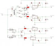
Hey guys, I hope you could help me with modding my Delta 1010's PSU. Below is a schematic that reflects the latest changes I have done. The circuit employs a voltage doubler that is used to generate +15V and -15V, and two half-wave rectifiers to generate the +5V rails. The 9VAC input is from a wall wart rated for 3.5A that converts the mains 110VAC to 9VAC. That is its rated spec but the actual input voltage I'm reading is 10.95VAC.
My problem is that I'm unable to get a clean voltage into and out of the +15V reg U4. The way I'm checking this is by measuring the AC voltage on the input and output of U4 (I don't have a scope). When I try to measure the voltage, I'm unable to get a reading because my meter fluctuates wildly. But I'm not getting this fluctuation when I measure the AC voltage on the input and output of the other regulators (they are giving me near zero AC voltage). I think this means something is wrong with either the +15V reg itself or the supply voltage going into it. Can someone please help me to sort this out? What are the things that I should check for? What other mods would you suggest to clean it up?
Any help would be greatly appreciated. Thanks in advance! 🙂
Attachments
Since no one is responding, maybe I should ask more specific questions:
1. What do you think of the value of C14 and C17 (currently 660uF). Are they too small? What value would you suggest?
2. What about the value of C12 and C18 (currently 3400uF). Are they too large? What value would you suggest?
3. Do you think it will improve the power supply if I replace all the UF4002 diodes with Schottky type MBR1100?
Someone help me, please!!! 😱
Hi,
try change c13 at output of u4 with 10uF and .1uF in parallel.
not correct big capacitance at output of regulators (autoscillation)
regards
try change c13 at output of u4 with 10uF and .1uF in parallel.
not correct big capacitance at output of regulators (autoscillation)
regards
Hi,
try change c13 at output of u4 with 10uF and .1uF in parallel.
not correct big capacitance at output of regulators (autoscillation)
regards
Thanks, I'll try that! 🙂 The .1uF should be a nonpolar, film or ceramic, right?
Thanks, I'll try that! 🙂 The .1uF should be a nonpolar, film or ceramic, right?
yes, ceramic 0,1 (100nF) is good
I want to experiment with changing the value of the capacitors C14 and C17. But first, I need to know what exactly is the function of these capacitors. Can someone please explain what these capacitors are doing in the circuit? Please be easy on me as I have only a little knowledge of electronics. I'm just handy with a soldering iron. 😱
Next question is the choice of the best capacitor for C14 and C17. I'm guessing that low ESR and high ripple current rating are some of the important considerations, and of course the voltage rating of the capacitor. I measured the voltage across C14 and it's only 13.6VDC. Therefore, I think that any voltage rating from 25V and up would be fine. I am currently looking at the following capacitor options:
Panasonic FM 820uF 25V, 0.018R Impedance, 2470mA Rated Ripple
- or -
Panasonic FM 560uF 35V, 0.018R Impedance, 2470mA Rated Ripple
I want to know which one of these would be the better choice. So the impedance and rated ripple of these are the same, the voltage rating is adequate for both, and the only question is the capacitance value. All things being equal, should I choose the one with the higher capacitance? Is higher capacitance a good thing and an important consideration for the function of this particular capacitor?
Thanks, and I hope someone could please kindly help me with this question! 🙂
Last edited:
C14 and 17 provide "DC" isolation and allow the the voltage on the end of the caps to develop... can't think of a better word.
Without them D2 and D3 would appear as a "short" to the 9vac winding, one conducting on positive half cycles and one on negative.
Caps... weird values you have chosen. I would use at least 2200uf for all. Having said that a lot depends on what current you intend to draw from the rails. Higher current = higher capacitance.
It's the voltage across C12 that matters... you need at least 18v for the reg to function correctly. Those 43 ohms are wastefull, any more than a few milliamps load current and the voltage to reg will fall dramatically. If you insist on resistors then I wouldn't go over 1 ohm non inductive type. C15 and C20 then need around 100uf cap in parallel with them.
C14 and 17 provide "DC" isolation and allow the the voltage on the end of the caps to develop... can't think of a better word.
Without them D2 and D3 would appear as a "short" to the 9vac winding, one conducting on positive half cycles and one on negative.
Caps... weird values you have chosen. I would use at least 2200uf for all. Having said that a lot depends on what current you intend to draw from the rails. Higher current = higher capacitance.
It's the voltage across C12 that matters... you need at least 18v for the reg to function correctly. Those 43 ohms are wastefull, any more than a few milliamps load current and the voltage to reg will fall dramatically. If you insist on resistors then I wouldn't go over 1 ohm non inductive type. C15 and C20 then need around 100uf cap in parallel with them.
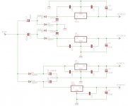
Hi, thanks for replying! 🙂 The value of C14 and C17 were even smaller before - only 470uF. Please see below the schematic of the original before I did any mods. So you mean I could use 2200uF or even higher for these caps? How about 4400uF? Is that too high? What's the maximum I can use?
I think the reason why the original designer put only 470uF for these caps is because of the heat. Increasing them probably reduces the ripple, causing an increase in the voltage going into the +/-15V regulators due to the cleaning of the ripple. In fact, I noticed that when I changed them to 660uF the input voltage to the regs increased by 1 volt. This increased the heat on the regs.
I've been getting too much heat on those regs that I had to put large heat sinks on them. Despite that, they were still very hot. The +15V reg would run at 63 deg.C and the -15V at 75 deg.C (measured by putting the temp probe on the large heat sink that I added). I measured the input voltages going into the regs, and the +15V reg was getting 25.7V, the -15V reg was getting 25.9V, one of the +5V regs was getting 13.1V, and the other +5V reg was getting 13.5V. The input voltages were just too much. I think the regs need only V output + 3 and anything in excess of that is just dissipated as heat. The heat was causing the capacitors to deteriorate quickly. That is why I put those resistors in, to reduce the input voltages, and thus the heat.
The way I calculated the additional resistors was by first putting a 1 Ohm resistor and measuring the voltage across the resistor while my Delta 1010 was loopback playing and recording a test signal on 8 channels (the Delta 1010 is an audio interface that has 8 analog inputs and outputs) to simulate full load. The test signal was generated by running 4 instances of RMAA, each instance playing and recording a stereo pair. So the first instance was playing a test signal on outputs 1 and 2, and recording them on inputs 1 and 2. The second instance was playing a test signal on outputs 3 and 4, and recording them on inputs 3 and 4. And so on with the third and fourth instances. This went on continuously while the voltage was being measured.
After getting the voltage across the 1 Ohm resistor, I calculated the current. Then based on the current that was calculated and the new input voltage that I would like to have, and the difference between the old and the new input voltage, I was able to calculate the appropriate resistor value to use. I came up with 43 Ohms for R4 and R5, 16 Ohms for R6 (I just realized the 27 Ohms shown on the schematic is a mistake), and 27 Ohms for R23.
After putting in these resistors, the input voltages I am now getting are 19V on the +15V reg, 19.6V on the -15V reg, 8.6V on one of the +5V regs, and 8.8V on the other +5V reg. With these resistors in place, I am no longer afraid of increasing the value of C14 and C17 and the resulting increase in input voltage that that would cause.
You mentioned that "C15 and C20 then need around 100uf cap in parallel with them". Does this apply only if I use 1 Ohm resistors instead of the values that I calculated? What cap value should I put in parallel with C15 and C20 if I'm going to use the resistor values that I calculated?
Thanks again! 🙂
Attachments
Last edited:
Caps used like C14 and C17 are prime suspects for faults... this type of circuit crops up frequently in varies guises.
Altering their values to tweek the voltage isn't good practice really... and as you say with the regs, you had way to much voltage applied.
No easy answer as it's all a compromise... and resistors will get hot too.
If you use any resistors, even 1 ohms then I would add 100uf or so at each reg input.
It maintains a low impedance as seen by the reg.
Edit... there's no "maximum" value as such. 2200 is low impedance at line frequency and a sensible size. I wouldn't go over that.
Last edited:
Caps used like C14 and C17 are prime suspects for faults... this type of circuit crops up frequently in varies guises.
Altering their values to tweek the voltage isn't good practice really... and as you say with the regs, you had way to much voltage applied.
No easy answer as it's all a compromise... and resistors will get hot too.
If you use any resistors, even 1 ohms then I would add 100uf or so at each reg input.
So, not just C15 and C20, I should add a 100uF in parallel with C24 also?
And what about on the input of U23? Should I add a 100uF across the input and ground of U23? BTW, why is there no capacitor like C24 on the input of U23? It seems strange. Is this a design error?
Edit... there's no "maximum" value as such. 2200 is low impedance at line frequency and a sensible size. I wouldn't go over that.
I'll use 2200uF then. Actually, I will parallel two 1100uF caps to make 2200uF. That will distribute the heat to two caps and will be a good thing because C14 and C17 are also prone to get hot. Due to the cramped space, however, I can only fit 25V-rated caps here. Is 25V good enough? (I currently measured 13.6V on these caps but I'm not sure if that might increase if I change them to 2200uF.)
I really appreciate your help. Thanks a lot! 🙂
It's good practice on any reg input to have both a small 0.1uf cap and also a larger electroylitic.
99% of the time they would work without either in practice, but adding them reduces the noise floor, reduces the impedance, and helps with the transient response of the regulator. The values aren't critical, small cap in the 0.01 to 0.1uf range and an electro in the 10 to 100uf range.
U23 should be decoupled as above.
The 2200uf caps !
The caps have reactance at AC as given by 1/2pi F*C
Reactance of a Capacitor
at 60hz it's around 1.2 ohms for a 2200 uf cap. A 470uf cap and it's nearer 6 ohms which is why the voltage of the doubler varies with capacitor values used.
Actual measured voltages can be unpredicatable because of the relatively poor regulation of a doubler so you will have to measure the voltage across the caps in use.
It's good practice to design for all eventualities so 25v might be marginal if there were no load on the PSU.
It's good practice on any reg input to have both a small 0.1uf cap and also a larger electroylitic.
99% of the time they would work without either in practice, but adding them reduces the noise floor, reduces the impedance, and helps with the transient response of the regulator. The values aren't critical, small cap in the 0.01 to 0.1uf range and an electro in the 10 to 100uf range.
U23 should be decoupled as above.
The 2200uf caps !
The caps have reactance at AC as given by 1/2pi F*C
Reactance of a Capacitor
at 60hz it's around 1.2 ohms for a 2200 uf cap. A 470uf cap and it's nearer 6 ohms which is why the voltage of the doubler varies with capacitor values used.
Actual measured voltages can be unpredicatable because of the relatively poor regulation of a doubler so you will have to measure the voltage across the caps in use.
It's good practice to design for all eventualities so 25v might be marginal if there were no load on the PSU.
Thank you so much, sir! 🙂 That is good education and most appreciated. Now I understand why the voltage of the doubler increases when C14 and C17 are increased.
My next question is, if a capacitor is getting hot, is it alright to put a large resistor across its terminals to act as a heat sink and help absorb the heat? Will there be no inductance issues or other bad side effects if you do that? If it's perfectly alright to do, I would like to know what would be the appropriate type (wirewound or metal film power resistor?), value and wattage of the resistor to use as a heat sink for the capacitors C14, C17, C12, C18, C22 and C60.
Thanks again! 🙂
Disaster, help!!!
Hi Mooly or anyone, I'm in disaster mode. The 100uF electrolytic cap I put in parallel with C20 exploded! 😱 This is on the input of the -15V reg U5. I made sure to connect the (-) terminal of the 100uF cap to the ground pin of the reg and the (+) terminal of the cap to the input pin of the reg. Did I do it wrong?
The latest changes I have done are: replaced C14 and C17 with 2200uF 25V, put 100uF electrolytic in parallel with 0.1uF ceramic on the input of the +5V reg U23, put 100uF electrolytic in parallel with C24 on the input of the +5V reg U6, put 100uF electrolytic in parallel with C20 on the input of the -15V reg U5. That's all. I did not put the 100uF on the input of the +15V reg U4 yet.
Is it possible that other things were damaged, not just the 100uF cap? Please help!!!
Capacitors don't in themselves disipate "power" as the current and voltage is 90 degrees out of phase.
Losses (heat) occur because the actual capacitor isn't perfect and has other properties that take it away from being "ideal" such as inductance, ESR etc
The reason why capacitors (theoretically perfect ones) dissipate no power on AC is because the current through the cap and the applied voltage across the cap are phase shifted by 90 degrees.
If a capacitor gets hot it's because the actual device chosen isn't suitable... or something else is physically heating it such as a nearby reg etc.
So you can't put any resistor across a cap at all... if they are getting hot it's because of either some external influence, or they are underated.
In your circuit C14 and C17 are the highest stressed parts. All the other caps should be essentially cold in use. The only current these other caps see is ripple which can't be that high.
Hi Mooly or anyone, I'm in disaster mode. The 100uF electrolytic cap I put in parallel with C20 exploded! 😱 This is on the input of the -15V reg U5. I made sure to connect the (-) terminal of the 100uF cap to the ground pin of the reg and the (+) terminal of the cap to the input pin of the reg. Did I do it wrong?
Please help!!!
You did it wrong... the input to the reg is at -25 or whatever volts... so that means with respect to that input pin ground is POSITIVE.
Ground is just a reference point... a common point. Voltages can be positive and negative with respect to this.
If you have done the same for other caps they will be reverse connected and that's why they are hot. Replace any that have been used like that.
The NEGATIVE terminal on the cap goes to the most negative point... which is the input to the reg.
Do you see ?
Measure on DC volts across ALL your caps in use to make sure they are all correctly fitted and within there ratings.
OK, for the positive voltage regs I connected the (+) terminal of the 100uF cap to the input pin of the reg and the (-) terminal to the ground pin of the reg. Is that correct?
So I thought the (-) terminal of the cap always goes to the ground pin. But now I know that for a negative voltage reg, the (-) terminal should go to the input pin and the (+) terminal should go to the ground pin! Oh my! I hope it's only the cap that got damaged. Do you think anything else might have gotten damaged?
BTW, I used 50V rated 100uF caps as they're the ones I have available. Thank you so much for your help!
Capacitors don't in themselves disipate "power" as the current and voltage is 90 degrees out of phase.
Losses (heat) occur because the actual capacitor isn't perfect and has other properties that take it away from being "ideal" such as inductance, ESR etc
The reason why capacitors (theoretically perfect ones) dissipate no power on AC is because the current through the cap and the applied voltage across the cap are phase shifted by 90 degrees.
That's good to know.
If a capacitor gets hot it's because the actual device chosen isn't suitable... or something else is physically heating it such as a nearby reg etc.
I think the latter is what's happening in my 1010's PSU. The space is so cramped and the input filter caps are very close to the regs. One particular cap that is getting very hot is C22, and this is a fault of the physical layout of the board. This cap is surrounded by three regulators - U6, U5 and U23.
So you can't put any resistor across a cap at all... if they are getting hot it's because of either some external influence, or they are underated.
My idea is based on how some circuits use a resistor across a capacitor to automatically discharge the cap when the power is turned off. Just that, in my case, the purpose of the resistor is not to discharge the cap but to act like a heat sink. It would be a fairly large resistor attached to the cap with very long leads so that the resistor would be located outside of the board's edge so it won't recirculate the heat it absorbs to nearby components. Is it a crazy idea? 😀
Other than that, can I buy a heat sink for a capacitor? Is there any such a thing?
In your circuit C14 and C17 are the highest stressed parts.
Yes, that's why I am changing each of these to two caps in parallel to distribute the heat over two caps. Another advantage is that, according to what I've read, two caps in parallel have lower ESR and higher ripple rating than a single cap of the equivalent value.
I wonder, though, what happens to the voltage rating when you parallel two caps? Say, for example, if you parallel two 25-volt caps, what would be the voltage rating of the combination? My guess is that it couldn't be the same but should be higher because voltage rating is heat related and the heat is distributed over two caps, thus the entire combination is able to take more heat. My question then is, how do you calculate the equivalent voltage rating of two caps in parallel?
Thanks! 🙂
Last edited:
It shouldn't have damaged anything else 🙂
Yes, it didn't damage anything else! 🙂 For a moment there I almost thought of giving up modding this thing, but now everything's fine and I'm back in business!
Thanks a lot! 🙂
Voltage rating of caps in parallel,
The voltage rating equals the lowest rated cap. Or if both caps identical then the voltage rating stays the same.
example, a 100 volt and 10 volt cap in parallel has a 10 volt rating. Two 63 volt caps in parallel still make up a 63 volt cap.
The capacitance value of parallel caps adds together.
The same voltage appears across each.
Caps should be run as cool as posible, however modern devices are rated to 105C. Check the markings.
Think you are misunderstanding cooling caps... it's not something that's generally done. The only way to remove heat is physically conduct heat from the body of the cap, you can not remove it "electrically" 🙂 The amount of heat two wires would conduct away would be negligable.
The ripple current is difficult to predict... two identical caps should share the current equally, in practice because the tolerances are so wide on caps they won't.
- Status
- Not open for further replies.
- Home
- Amplifiers
- Power Supplies
- Need help on Delta 1010 PSU mods