Greetings everyone,
I breadboarded a P-P 6DQ5 amplifier with a 6SN7 voltage amp. I coupled with a 1:3 transformer. The output transformer was a 15W 8K:4 transformer.
I used 500vdc on the plate and 175vdc on the screen of the 6DQ5 and 175vdc on the plate of the 6SN7. I adjusted the bias for an idle current of 32ma/tube on the 6DQ5. So, considering the output transformer is not even close to what the 6DQ5s wants to see, the amp was LOUD. Real LOUD. I ordered 3.3K 100W transformers from Edcor. We'll see how things change with them.
Ray
Last edited:
Try paralleling two 4R speakers until those transfiormers arrive. This will give you a better idea of what you should expect with them.
Post the schematic when you finish your design, I'm sure others would be happy to see it and perhaps offer some suggestions.
Post the schematic when you finish your design, I'm sure others would be happy to see it and perhaps offer some suggestions.
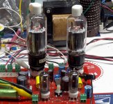
OK, it is Sunday and for the first time since July 4 I am not at work. So....time to make 'em glow. I had guessed that the 6DQ5 would make about 100 watts at 550 volts and a 3300 ohm load without melting. Speculation on the bias current was 30 to 40 mA.
So I wired a pair of 6DQ5's into the red board, set the screen supply at 150, the plate supply at 550, and adjusted the bias current for 30 mA. I applied enough signal to get 1 watt and tweaked the bias current and the balance for minimum distortion. 0.37% distortion comes at 33 mA and more or less current raises the distortion although it remains under 0.5% from 27 to 50 mA.
I then applied more crank. As the input signal went up, so does the output power and the distortion. 50 watts makes 1.89%. 100 watts gives 3.27%. I usually state amplifier power as the power at which the distortion crosses 5% which comes at 107 watts. Crank it till square waves appear reads 129 watts although this is not an accurate number.
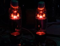
The tubes show a faint glow if left at 100 watts for several minutes in a dark room. Since the power goals were met at 550 volts, I see no reason to go higher since more glow would appear, or the bias current would need to be reduced.
So I wired a pair of 6DQ5's into the red board, set the screen supply at 150, the plate supply at 550, and adjusted the bias current for 30 mA. I applied enough signal to get 1 watt and tweaked the bias current and the balance for minimum distortion. 0.37% distortion comes at 33 mA and more or less current raises the distortion although it remains under 0.5% from 27 to 50 mA.
I then applied more crank. As the input signal went up, so does the output power and the distortion. 50 watts makes 1.89%. 100 watts gives 3.27%. I usually state amplifier power as the power at which the distortion crosses 5% which comes at 107 watts. Crank it till square waves appear reads 129 watts although this is not an accurate number.
The tubes show a faint glow if left at 100 watts for several minutes in a dark room. Since the power goals were met at 550 volts, I see no reason to go higher since more glow would appear, or the bias current would need to be reduced.
Attachments
Hey George,
Thanks for the info. I'll reduce screen to 150vdc and see what happens. So my question for you is at the 100w level you were getting 3.27% distortion, is that with or without feedback and if it is without, how much lower would the distortion be and what is the price on power.
Thanks,
Ray
Thanks for the info. I'll reduce screen to 150vdc and see what happens. So my question for you is at the 100w level you were getting 3.27% distortion, is that with or without feedback and if it is without, how much lower would the distortion be and what is the price on power.
Thanks,
Ray
The red board uses both local (Schade) feedback and Global Negative Feedback. I am using the local feedback which is a resistor from the plates of the output tubes to the plates of the driver tubes. This lowers the output impedance without sucking the life out of the sound. I am not using the GNFB on this board since all of my listening tests have sounded better without it despite slightly higher measured numbers. Applying negative feedback will not reduce the available power output. It will reduce the total amplifier gain so that you will need more input voltage for a given power output.
Regarding the Kepco power supply, I have one and it is working, but it has been banished to the warehouse since the big HP came to town. Too many power supplies, not enough bench space. I don't know if I will get there before leaving town next weekend.
Got to crank up some more tubes before dinner. I should have more info tonight but I will post to the red board thread.
Thanks for your help George! Last question, you posted some distortion numbers. At what point does it become noticable? Is 3.27% noticable?
Thanks,
Ray
Thanks,
Ray
Perhaps you should have a look at http://www.diyaudio.com/forums/tubes-valves/171047-variable-harmonizer.html]this topic, especially the pages beyond 2nd. Not all THDs are created equal, mr. Jefferson said 😀
At what point does it become noticable? Is 3.27%.......Not all THDs are created equal
As most people know not all DISTORTIONS are created equal. Unfortunately most THD meters including my multi-killobuck (when new) HP do not measure THD. Most meters measure the level of the fundamental tone, then engage a sharp notch filter to remove it, measure what's left, and compute the total distortion. This includes THD, IMD, hum, noise and anything else that is not the applied tone. An FFT analyzer running on a PC will provide a visual display of all of the frequency components in the output spectrum of the unit under test. Mine is non functional at this time.
Lets review a bit about distortion:
First there is "THD" Total HARMONIC Distortion. THD is the sum of all of the harmonics created in the unit under test, measured and referenced to the total output. All harmonics do not sound equally displeasing.
The second harmonic is a tone exactly one octave above the original tone. If the amp is fed "A above middle C" (A4) as played on the piano (440 Hz) the second harmonic will still be an A. So will the 4th and all of the even harmonics. Most agree that a reasonable amount of even harmonics are tolerable and even pleasing. After all look at all the SE amps.
The third harmonic usually falls very close to a note that sounds pleasing when played with the original tone. The third harmonic of A4 is 1320 Hz this is very close to E6 (1318.5 Hz) and an A and a E form a pleasing chord. So some 3rd harmonic within reason is usually not objectional. The 5th harmonic does not fall close to any musical note at all thus sounds dischordant to those used to the 12 tone musical scale. Ditto the higher odd harmonics.
There is also InterMoDulation distortion. No amplifier is perfectly linear. Theory tells us that whenever two signals are applied to a non linear device 4 (or more) signals will be present in the output. The two original signals, plus the mathematical sum and differences of their two frequencies. Apply a 440 Hz piano tone and 55 Hz thump from a bass guitar (both "A" notes) and you will get 385 Hz and 495 Hz. These are usually dischordant.
THD and IMD usually occur together so you will get the IMD mixing products of the input tones AND all of their harmonics too. We all know that hum and noise sound bad. Yes, the hum will IMD with the input tones too. There are also many more types of distortion, including some that we don't even know how to measure yet.
There is also a lot of psychoacoustics at work here. If you are cricitally listening to a piece of simple music at a low volume level it is easy to notice some simple nuances including distortion. If you are in the mosh pit at a Metallica concert (yes I have been there) can you tell the difference between 5% and 10 % distortion? I don't think so. SO...
If you have a very good system and you were listening at a reasonable level could you hear 3% of pure second harmonic? Maybe, maybe not. You might notice it especailly if you always listened to a SS system with .005% distortion. Could you hear even 1% of pure 5th harmonic at the 1 watt level. BIG TIME! Could you hear the difference between 1% and 3% assuming a reasonable harmonic spectrum? At 1 watt maybe. At 100 watts. NO your ears are saturated and probably generating even more distortion.
Music has a lot of dynamic range. The differences between the loudest and the quietest parts can be 50 to 80 db. When designing RF amplifiers for cellular and other communication systems, we speak of the peak to average ratio. Most music has a peak to average ratio of at least 20 db. Simply put, this means that if you took your 100 watt amp and turned it up until it just clipped the ocasional peaks, the AVERAGE power being produced will be 1 watt or less. What does this mean? As stated in the name of a high end solid state amp it is the FIRST WATT that counts. It MUST be clean. If the amp puts out 3 or 5 or 10 percent or even clips a bit at 100 watts who cares AS LONG AS IT RECOVERS QUICKLY and gracefully.
BTW, I measured 0.37% at 1 watt and even tweaked for minimum distortion at this level. Now you know why.
George, what do you think about driving the DQ5's with the circuit used in the thread "6L6GC AB2 AMP"? When you drove the DQ5's to 100W, were you in AB1 or 2?
Thanks
Ray
Thanks
Ray
Hello George,Music has a lot of dynamic range. The differences between the loudest and the quietest parts can be 50 to 80 db. When designing RF amplifiers for cellular and other communication systems, we speak of the peak to average ratio. Most music has a peak to average ratio of at least 20 db. Simply put, this means that if you took your 100 watt amp and turned it up until it just clipped the ocasional peaks, the AVERAGE power being produced will be 1 watt or less. What does this mean? As stated in the name of a high end solid state amp it is the FIRST WATT that counts. It MUST be clean. If the amp puts out 3 or 5 or 10 percent or even clips a bit at 100 watts who cares AS LONG AS IT RECOVERS QUICKLY and gracefully.
BTW, I measured 0.37% at 1 watt and even tweaked for minimum distortion at this level. Now you know why.
Thank you for the distortions and average level to peaks insights. Do you have any light to shine on the compression / loudness wars for current CD’s and vinyl vs vinyl back in the day?
DT
All just for fun!
George, what do you think about driving the DQ5's with the circuit used in the thread "6L6GC AB2 AMP"?
It's on my list of things to do. Unfortunately it is a long list.
The driver board I made during that thread is the best that I have ever made using two cascaded LTP's made from triodes. It uses mosfet followers to allow unlimited grid current for AB2 and screen drive. The followers eliminate grid blocking distortion and the associated recovery issues. It would probably produce a little more power, and better transients than a simple driver.
When you drove the DQ5's to 100W, were you in AB1 or 2?
The red board uses RC coupling to drive the output tubes. In theory this will not work for AB2. In practice I have seen the grids go slightly positive on the red board. I did not scope the grids when the 6DQ5's were in there. They have been swapped for E130L's right now.
I got Petes red board almost a year ago. I still play with it. For someone as attention deficit as me, that is an eternity. Why, because I am still learning things, and there are still things about the board that I don't completely understand. I have learned enough to know that I need to do some more experiments which will result in yet another driver board. The red board runs out of gain when asking for big power out of sweep tubes. A CD player will not drive it to clipping. The red board doesn't have mosfet followers. Sooner or later I will make another driver board. I must then test it against the driver board from the AB2 thread. Which will win? I don't konw. Even then, there will always be another one.....
Do you have any light to shine on the compression / loudness wars for current CD’s and vinyl vs vinyl back in the day?
A vinyl record is limited by noise on the low end, and tracking errors on the high end. I had to increase the tracking force on my turntable when the Led Zepplin Two album came out because the bass on Whole Lotta Love would toss the needle right out of the groove. The best dynamic range was 50 to 60 db then. A modern CD is capable of dynamic range in the 90 db range. Do the recording engineers use it wisely? No they still compress and squash the life out of most recordings. Why? Because 95% of their listening (and buying) audience uses junk equipment that couldn't reproduce it anyway. They probably use the same mix to make MP3's.
Nearly 40 years ago I got a tour of Criteria recording, a famous studio in Miami. The mix down engineer had several nice sets of studio monitor speakers on the deck over his console. He also had a pair of 6 X 9 inch car speakers mounted on plywood behind his chair. I asked why? He responded that much of his music would be heard on an 8 track player in a car through 6 X 9 speakers mounted in the deck behind the rear seat. He had to make sure his mix sounded good through that!
Did some more testing, found a hefty transformer with a 2500 ct primary. Put 515v on the plates, 150v on the screens. set bias for 40ma/tube. Fed the grids with a 1:3 interstage transformer that had an mp3 player hooked to it. All I can say is wow. The plate current did not move off of 80ma, but it was really quite loud. Loud enough to cause the ears to hurt. I fed two 12" speakers.
George, when you get a chance, please check your email.
Thanks,
Ray
George, when you get a chance, please check your email.
Thanks,
Ray
The 5th harmonic does not fall close to any musical note at all thus sounds dischordant to those used to the 12 tone musical scale. Ditto the higher odd harmonics.
Square waves (containing all odds) do not sound "dissonant" to me,
they just sound like square waves... The 5th harmonic is Major 3rd.
The 3rd Harmonic is Major 5th. So by definition, a MAJOR chord.
I will not dispute that just tempered harmonics with roots other
than 2, may not line up well against evenly tempered "notes" in
octave scale. Especially when several octaves are spanned. Fact
of math irrelevant to your assumption that just harmonics should
sound dissonant when played in the strong presence of their own
root. Even to someone untrained in other scales.
The untrained ear goes for just over evenly tempered every time.
Why beginners have such trouble setting up an evenly tempered
intonation on a guitar. Wolf Fifth eats em' alive!
Harmonics are always musical. IMD sometimes, sometimes not....
Play you a pure triangle wave (all evens), musical....
Play you a pure square wave (all odds), musical....
Play together (odd vs even roots diverge?), musical, go figure!
Any IMD on that last experiment would probably mix terrible?
----
OK, I'm wrong here. Pure triangles consist only of odd harmonics
just like squares do.... What waveform consists of the all evens?
Last edited:
Common even harmonic series in tables are half wave rectified sine waves and half wave rectified triangle waves. But notice that you can shift one and add it to back to itself to get back a full wave series, which is given by an odd harmonic series. So you could get the full triangle wave series (odd H series) back from two half wave rectified triangle waves (offsetted even H series) What gives? Magic? No, a triangle wave is an odd series for the fundamental and an even series for 1/2 the fundamental.
[SNIP!
Nearly 40 years ago I got a tour of Criteria recording, a famous studio in Miami. The mix down engineer had several nice sets of studio monitor speakers on the deck over his console. He also had a pair of 6 X 9 inch car speakers mounted on plywood behind his chair. I asked why? He responded that much of his music would be heard on an 8 track player in a car through 6 X 9 speakers mounted in the deck behind the rear seat. He had to make sure his mix sounded good through that![/QUOTE]
Yamaha NS-10's live on for the same reason...
Thank you ,Barry Gordy !
- Status
- Not open for further replies.
- Home
- Amplifiers
- Tubes / Valves
- Initial 'DQ5' testing