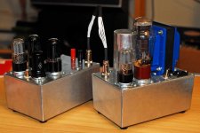
So I've been very busy this summer, currently I got a Phono Preamp, a 56 Preamp, and now a 6V6 push pull amp. Here are some pictures and a schematic. I have to thank the community, I don't recall how many times I've read about what happens if you mix up the primary connections on a push pull opt, it saved me a bunch of time when one of the channels oscillated. I constructed each mono block in two chassis. I like having the PSU and amp separate so that I trouble shoot them separately. My first impressions are favorable. I built it as shown but with the addition of some carbon comp grid stoppers on the 6SJ7 and 6V6s. The only issue I have is that it runs about 30 volts low (still sounds good, I just wish I was getting full power). It was worse but I swapped out some 5AR4s for the 5U4s. The power transformer is an Edcor XPWR057 210v-0-210v, 120ma. Any ideas? I thought it would run hot if anything because it was over spec'ed. Maybe I'll switch to SS rectification.
Athos
One thing that surprised me was how quiet this little guy was...
Athos
One thing that surprised me was how quiet this little guy was...
Attachments
The use of regulated screens is a good idea. If you get the urge, it wouldn't be too hard to improve the regulator portion.
As for the low voltage... did you check your mains?
As for the low voltage... did you check your mains?
Athos, that's a super looking PP amp with a good layout.
Nice to see the tube rectification 🙂
Congratulations! Konstantin.
Nice to see the tube rectification 🙂
Congratulations! Konstantin.
Athos,
Very nice work. Congratulations. I found that schematic last night when I was looking for adjustable self bias ideas. Does that feature work well in your amps?
Suggestion: Try rolling some 6SJ7GTs.
Very nice work. Congratulations. I found that schematic last night when I was looking for adjustable self bias ideas. Does that feature work well in your amps?
Suggestion: Try rolling some 6SJ7GTs.
The use of regulated screens is a good idea. If you get the urge, it wouldn't be too hard to improve the regulator portion.
As for the low voltage... did you check your mains?
Thanks for the comments. Sy, my main's voltage is a solid 120vac. I was thinking that the 20k bleeder is dragging the voltage down? Is it calculated to work with the regulator? What were your suggestions for regulator improvements?
Dtut, I have my expendable Russian tubes in now, I look forward to rolling some.
Athos
The amp looks great.
While it looks like you did something with heater to cathode voltage, I might derive it locally in case the preamp is powered down or the connector falls off.
Congratulations on avoiding the mistake of a large first cap after the tube rectifier.
Very nice.
Doug
While it looks like you did something with heater to cathode voltage, I might derive it locally in case the preamp is powered down or the connector falls off.
Congratulations on avoiding the mistake of a large first cap after the tube rectifier.
Very nice.
Doug
Last edited:
The amp looks great.
While it looks like you did something with heater to cathode voltage, I might derive it locally in case the preamp is powered down or the connector falls off.
Congratulations on avoiding the mistake of a large first cap after the tube rectifier.
Very nice.
Doug
Thanks! In fact I did use a voltage divider to float the heaters on ~1/4 B+
I resisted tinkering with the PSU, I didn't think there was enough filtering at first, but these are the quietest amps I've built. I learn more every time.
Athos
What were your suggestions for regulator improvements?
Right now, the tube is configured as a cathode follower pass element and has a pretty high source impedance. The control signal is a slightly divided and bypassed version of the ripply, noisy input voltage. You have several upgrade paths- you can convert this to a feedback regulator by adding another control element (see, for example, Jan Didden's T-Reg, which could work perfectly with the tube and socket you've already got in place).
A higher transconductance pass tube would help- the 6AS7 is a classic choice.
The very easiest upgrade would be to use a Zener reference at the grid, with an RC filter between the reference and the grid. That's not a great regulator, but it's definitely a step up from no regulation.😀
The very easiest upgrade would be to use a Zener reference at the grid, with an RC filter between the reference and the grid. That's not a great regulator, but it's definitely a step up from no regulation.😀
It looks more like an active decoupler. Replacing the half of a 6SN7 with an N-Channel MOSFET would be an improvement. Even better would be real active regulation.
Well, yes, I assumed the OP wanted to keep a tube as pass element and a tube rectifier. If it's more a matter of pure power supply performance, a solid state reg is better.
Looks like some heavy NFB employed with the 1K resistor.
Looks like about 17dB. That's probably not too far from what you'd want in a an amp with a pentode output circuit.
Hi,
just a small question, what is the connector you used to bring HV and heater supply to the amp ( the shiny thing you have with white cables on your photo)? I want to build something else with the separated power supply so I am looking for solutions...
Thanks,
Pred
just a small question, what is the connector you used to bring HV and heater supply to the amp ( the shiny thing you have with white cables on your photo)? I want to build something else with the separated power supply so I am looking for solutions...
Thanks,
Pred
Hi,
just a small question, what is the connector you used to bring HV and heater supply to the amp ( the shiny thing you have with white cables on your photo)? I want to build something else with the separated power supply so I am looking for solutions...
Thanks,
Pred
It is a 8 pin connector, you can get them at "The Shack." I think they are for mic cords. I lock tighted the psu side.
Any alterations will have to use what I got on hand, Which is half a 6sn7 in each chassis, and an assortment of resistors/caps/ss stuff. I may also try ss rectification, and and I might roll a 6as7 in the psu. Is there any benefit in tinkering with the feedback?
Athos
Looks like some heavy NFB employed with the 1K resistor. How's your gain structure ?
The gain is pretty low, I can turn my 56 pre up about half way, with my Moskito amp the cops would be called by that point. The 6v6s should put out over 10 watts and the Moskito about 16 watts. I was also looking into getting a little more umph out of my 6SJ7s.
Athos
Athos,
(hand waving from the back of the crowd) Did you do the OP cathode bias as drawn? Did it work?
(hand waving from the back of the crowd) Did you do the OP cathode bias as drawn? Did it work?
<snip> The only issue I have is that it runs about 30 volts low (still sounds good, I just wish I was getting full power). It was worse but I swapped out some 5AR4s for the 5U4s. The power transformer is an Edcor XPWR057 210v-0-210v, 120ma. Any ideas? I thought it would run hot if anything because it was over spec'ed. Maybe I'll switch to SS rectification.
Athos
One thing that surprised me was how quiet this little guy was...
The original transformer was specified incorrectly, considering that the peak value of 200Vrms (400VCT) is only 282Vpk, subtract the rectifier losses and you would get something on the order of 260 - 270V depending on the rectifier used. Your 210V-0-210V (420VCT) transformer if lightly loaded (depending on winding DCR) could get you to just about 300V under slightly high line conditions. Solid state rectification will get you closer still.
The best bet would be to replace that power transformer with something like a 480VCT transformer. (It's not too critical)
Last edited:
Sorry, I missed you.
Yes, I did do it as drawn. It works well, I measured at the two ends of the pot and adjusted for until I got the same voltage. I believe that is the proper thing to do. I used 1% resistors so the pot ended up smack in the middle.
Sorry again.
Athos
Athos,
(hand waving from the back of the crowd) Did you do the OP cathode bias as drawn? Did it work?
Yes, I did do it as drawn. It works well, I measured at the two ends of the pot and adjusted for until I got the same voltage. I believe that is the proper thing to do. I used 1% resistors so the pot ended up smack in the middle.
Sorry again.
Athos
The original transformer was specified incorrectly, considering that the peak value of 200Vrms (400VCT) is only 282Vpk, subtract the rectifier losses and you would get something on the order of 260 - 270V depending on the rectifier used. Your 210V-0-210V (420VCT) transformer if lightly loaded (depending on winding DCR) could get you to just about 300V under slightly high line conditions. Solid state rectification will get you closer still.
The best bet would be to replace that power transformer with something like a 480VCT transformer. (It's not too critical)
Your math is impeccable, I'm impressed. I switched to diode rectification and a 6as7 and am getting exactly 282v on my b+ and 262v on my screen. This is very reassuring because I have one of your tube regulators in the works 🙂.
That sucks about the transformer. I have a few options (read beafier transformer) for a single supply for both channels. I would use your regulator or a reg made from a LR8N and a TIP50 for the B+, and screen.
Good thing is that they still sound pretty good.
Athos
- Status
- Not open for further replies.
- Home
- Amplifiers
- Tubes / Valves
- Finished my first PP amp, 6SJ7-6SN7-6v6