Dera Gerd,
I try BA-2 , because I don't have big big enought heatsink.
If you want to drive lower than 4 ohm speaker on BA-1 , you need to double the bias current on the output Mosfet. In case will double up the HEAT from Mosfet .Otherwise your picture will be getting smaller and smaller.
I try BA-2 , because I don't have big big enought heatsink.
If you want to drive lower than 4 ohm speaker on BA-1 , you need to double the bias current on the output Mosfet. In case will double up the HEAT from Mosfet .Otherwise your picture will be getting smaller and smaller.
I want to build a little bit higher power of BA-2.
At +/- 35v rails with cascading input jfet. But I don’t know how to do the cascade.
Dose anyone can post the cascading circuit diagram ?
Thanks
At +/- 35v rails with cascading input jfet. But I don’t know how to do the cascade.
Dose anyone can post the cascading circuit diagram ?
Thanks
I believe the BA-2 article says that up to 35V is possible but 30V is the highest recomended. Com'on, it's a Burning Amp 😀
Actually, I'm going this way too. I want to build something more suited to 8 ohm nominal loads. But, I think I will try it without the cascodes. My supply does just over 33V loaded. It will probably be a while though. I'm doin the pack up and move thing again. 🙁
Dear Flg,
If +/- 35 rails voltage will makes the amplifier burn, Of course I will try it. But it won't. May be I can only hear a 'POP' sound comes form the input jfet and heart bit form my-self .
Anyway, Thanks your advise .
If +/- 35 rails voltage will makes the amplifier burn, Of course I will try it. But it won't. May be I can only hear a 'POP' sound comes form the input jfet and heart bit form my-self .
Anyway, Thanks your advise .
Dear Flg,
If +/- 35 rails voltage will makes the amplifier burn, Of course I will try it....Thanks your advise .
Like I said, 30V is a suggested max. Read the BA-2 Article. I'll go do it again right now... While I listen to NHRA drag racing on the www. There is a gate leakage spec that is not neccesasrily a spec we are concerned with that is the reason for the 25Volt BVvds. We should understand that better here but I don't because it's Friday night and I'm busy doing other stuff...


well - I take a look only on cascode related parts ;
of course - you're right about value of R205 - it must be in range of 3K6-3K9/1W
of course - you're right about value of R205 - it must be in range of 3K6-3K9/1W
I don't know why you say it should be 3.6k to 3.9k for R205 the difference as I see it, is a current through R205 of approx.12.2ma with power of .581w for R205 = 3.9k vs. a current of approx 4ma and power of .196w. Is there some magic current value for the 2sk170 for the sweet spot? The foward transfer admittance will be a little lower with the lower current but is that a problem?
I understand, or think I do The drop across R205 at 4ma and 12k is approx. 48 volts.
The bias at source of q202 is approx. -20ma the drop across q202 is around .4 volt. Or have I got the whole thing wrong. The way I have it figured is there is around 24.4 volts drop across the 2sj74's q101 and q201, which is pushing the voltage so I will change the voltage divider on Q2 and Q1 to around 3700 and 6250 ohms which should give me a drop across q101 and q201 of around 18 volts. If I am all wet on this please let me know.
Thanks for responding.
q202 is wired as a CCS.
It will try to pass it's Idss if the Drain to Source voltage is ~ 10V.
If Vds<10V then it will pass less than Idss.
If Vds <<10V then we have little idea what current it will try to pass. It might be 2mA or 4mA or 6mA rather than near Idss.
Let's assume Vds ~ 1V.
Then Vr202 ~ 49V.
Ir202 ~4.08mA.
is our assumption correct?
I can see a way to check. Measure the Vds of the jFET. Check the voltage & current through R202.
If the jFET has <<10Vds then it cannot act as a CCS. the 12k take over control of the current flowing to the pair of transistors of the LTP.
The 12k is too high. Reduce it to somewhere around 6k8 to 10k and measure the Vds of the jFET and use the voltage across the new resistor to determine the current flowing to the LTP. If Vds is still <<10V then reduce the resistor even more or select another jFET with a lower Idss if that suits the LTP design requirement.
24V across a jFET LTP is too high. much too high.
Most recommend a cascoded jFET to run from 2Vds upto 10Vds
Last edited:
q202 is wired as a CCS.
.......
Most recommend a cascoded jFET to run from 2Vds upto 10Vds
yup ;
probably same ppl who recommend using 6DJ8/ECC88 fed with 30V from anode to cathode

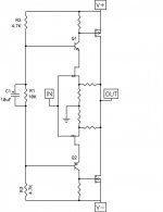
BA2 cascode front end
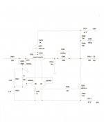
Ok here is latest cut on cascode frontend for BA2. (refer to schematic)
1. Power supply + - 50volts
2. Assume 2sk170 IDSS 12.4ma
3. Postive rail 47.9v, negative rail -47.7v (measured after r210 and 4211)
Then the drop across r205 (3k)= 37.25v, the drain of q202 =10.65v, the source of q202=-0.214v, r205 power= 0.463w, power q202=0.135w.
2sj74's drain=-11.1v, source=-0.214v, power 78mw. Base of 2n3906 -11.8v,
collector= -40.5v power 0.210w, p201 at 1k=7.15ma, power 51mw.
Gate of IRF610 =-40.5v, source=-44.5v, drain=0.879, power =1.42 w.
r207=31.35ma, 98mw. r208 and r209 0.737w. If the Idss of q202 the values
need to be adjusted slightly but I think this should be in the ball park.
With +- 50volts this should allow around 80 to 90 watts at 8 ohm.
40volt swing =28.3 vrms =100watts at 8 ohm.
Attachments
- Home
- Amplifiers
- Pass Labs
- Burning Amplifier BA-2