I'm using a 4-ohm 200w resistor from Parts Express as a dummy load to measure the power output of an amp. On the first test the output was just below clipping on the scope at 29.2 volts. I immediately disconnected and measured the hot resistor and got 6.2 ohms, for 137 watts. As the resistor cooled it slowly came back to the starting 4.2 ohms.
On the second test (same channel), the amp was again just below clipping at 29.2 volts, but this time when I measured the hot resistor it was at 0.9 ohms. As the resistor cooled the resistance slowly ROSE back up to 4.2 ohms.
What the heck is going on? I'm so confused I don't even know where to start. Is it possible that I cooked the resistor during the second test and this resistor's failure mode allows resistance to drop? That seems counter-intuitive and downright dangerous. I repeated the test a third time and got the same result, and the resistor heated up much faster which seems to support that the resistance has dropped and is dissipating more power. However, the DUT is a cheap 10 year old Pioneer receiver. It did not go into protect mode. How could it possibly have been delivering almost 950 watts (even given that I was only loading one channel)?
I would greatly appreciate any insight or suggestions. This is my first post here, and I'm new to electronics so please forgive (and correct!) me if I say or ask something stupid.
Thanks!
The resistor may be shorted between turns. When this happens with non-inductive (inductance cancelling) resistors, can you lose a substantial part of the resistance element, not just a single turn, depending on where the short is. And its power handling drops into the toilet, too.
Hi,
metal resistors have a positive temperature coefficient. They are a few special alloys that have a slight negative tc, but they are rare.
That's why Tungsten filament lamps generally fail at start up rather than while being used. They demand an enormous start up (cold) current that rapidly drops by ~60% as the filament reaches incandescence.
When cold the wire in the core of your resistor has a cold value resistance.
That's the 4r2 you are measuring.
As you heat it up the resistance rises.
The amplifier starts by applying ~30Vac to the 4r2 resistor and heats it up.
The resistance rises and the amplifier sees an easier load, now 5ohms and rising.
This allows the amplifier to keep working into that test load without blowing up.
It looks like you have some spurious measurements.
You must keep the amplifier cold or at worst cool during and through out testing. Similarly you must keep your test resistors within their resistance specification by ensuring they too never heat beyond the temperature that significantly changes their resistance.
A short one second test at high output will bring the PSU down to it's continuous duty voltage and allow a measurement to be taken before significant heating has occurred. switch off the test signal. Let everything cool while you write down the result. Change your test condition and do another one second test.
How big is the heatsink you have attached to your 200W resistor?
Without a heatsink it may be rated as low as 1W to stay within 1% of it's rated resistance.
How are you measuring 4r2, 6r2, 0r9? That may be part of your problem with spurious results.
Last edited:
Thanks for the responses.
wg_ski, are you saying that the turns would be shorting as they heat up and expand, hence the dropping resistance while under load and then rising again while cooling? I measured it a number of times, it seemed to be a pretty slow and steady rise (not sure about the rate while dropping).
AndrewT, this is the resistor - 4 Ohm 200W Non-Inductive Dummy Load Resistor | Parts-Express.com. The heatsink is just the aluminum case, which appears to be filled with sand and resin. I let the amp drive the load for quite a while - I slowly ratcheted up the output until I saw the signal begin to clip on the scope, then I turned it down, confirmed the voltage. The second test it was on for even longer as I was trying to figure out what was going on. I measured the resistance multiple times with a handheld DMM, and also with the CLIO Sc-02 & 8.5 software.
I'm pretty confident in the resistance measurements, but that still leaves me with two highly unlikely possibilities. Either the crappy Pioneer managed to deliver 950 watts, or both CLIO and my DMM are giving false but consistent readings.
The resistor would need to have horrifying temperature coefficient to explain these results. I cannot give a definite answer either but I suggest you look at your resistance measurement which seems a potential source of error.
To measure resistance below 100 Ohms with decent accuracy you need Kelvin sense (4 wire) connections which I presume you have not. Also a simple DMM will measure resistance at rather low current, which means that the voltage across the resistor will also be low (which allows in-circuit measurements without turning on paralleled diode junctions). What's the lowest range of your DMM? If its something like 1k the voltage across a 4r2 resistor will be very low. This makes the measurement sensitive to thermoelectric voltages generated at the resistor leads. As the resistor cools down these dissapear and the resistor measures as it should.
I suggest you alternatively measure the resistance by passing some more current through it. Connect it in series with a 200 Ohm/0.5 W resistor and apply 10 V across the combination. Some basic U = R*I calculations will reveal the resistance.
As I said: I'm guessing too and I'd be surprised if the thermoelectrics are that strong. But I don't have any better idea right now.
Samuel
Thanks, I will try that. The lowest range on my DMM is 200. I used essentially the same leads with CLIO and the DMM, so it sounds like that could be the problem.
Just so that I have a frame of reference, anyone have an idea how much should I expect a resistor of that size to vary in resistance with a reasonable temperature increase within it's rated power - i.e. if it were dissipating 150 watts for 3 minutes would an increase from 4r2 to 6r1 be expected? More? Less?
Just so that I have a frame of reference, anyone have an idea how much should I expect a resistor of that size to vary in resistance with a reasonable temperature increase within it's rated power - i.e. if it were dissipating 150 watts for 3 minutes would an increase from 4r2 to 6r1 be expected? More? Less?
wg_ski, are you saying that the turns would be shorting as they heat up and expand, hence the dropping resistance while under load and then rising again while cooling? I measured it a number of times, it seemed to be a pretty slow and steady rise (not sure about the rate while dropping).
The rate while dropping would probably be a lot faster. If it is shorting, it may get more and more erratic with thermal cycling and then fail altogether. I had one literally explode and shoot the flaming guts out the end of the metal case.
I doubt that measurement accuracy is at fault. We're not talking about tenths of ohms here. It's normal for resistance to double with a 200C temperature rise and a DMM can resolve this easily.
Your resistor may be an exception but most aluminum housed resistors need to be on a heatsink with thermal compound. I just looked up one 200w aluminum housed resistor that spelled this out. Without a big heatsink the device was derated to 50W.
I have some Dale metal clad 50W resistors that measure about 4" X .75" and I think
they call for being on a 6" X 8" piece of aluminum to live up to the 50W rating. Don't
quote me there that was from something I read years ago. So I bet your restor just
died....
I have some Dale metal clad 50W resistors that measure about 4" X .75" and I think
they call for being on a 6" X 8" piece of aluminum to live up to the 50W rating. Don't
quote me there that was from something I read years ago. So I bet your restor just
died....
Interesting. wg_ski, was it the same Parts Express resistor (not sure who makes it) that failed/exploded on you? Did it display this same drop in resistance BEFORE it exploded?
for that sort of load, mount the dummy load on a ali plate as suggested and then force cool it with a fan - an old PC 12v one will do fine.
I use this for my dummy load and have had no problems - the resistors are rated 100W 6ohm (stereo load) and they stay below 50C when running 100 watt sine into both at the same time, 200W total dissipation. I would not run them without the fan over 20watts input
I suspect the resistor is cooked as a previous poster mentioned
Would an increase from 4r2 to 6r1 be expected?
For the part we don't have any reasonable data but I'd say its safe to assume a worst-case tempco of 500 ppm/K (anything more qualifies as thermistor). That means for a 50% increase we'd need to heat it by 1000 K--no, you'll see fire before that.
I second that full power stress of this resistor will likely ask for either a heatsink or forced air cooling. But 3 min ain't that long either. On the other hand the price suggests it's not a quality part so perhaps indeed it just died.
Samuel
On the other hand the price suggests it's not a quality part so perhaps indeed it just died.l
Understood. Any recommendations on brand?
Spiny, what are you using in the setup you described?
If the thermoelectric effect is causing confusion then would not this change sign if the meter leads were swapped over? Does this explain why it sometimes appears to go up when hot, and sometimes down?
So get it hot and measure with the leads both ways round. You might find that one way it is 2ohms high and the other way 2ohms low.
So get it hot and measure with the leads both ways round. You might find that one way it is 2ohms high and the other way 2ohms low.
no heatsink = failed test. And probably failed resistor.
So that raises two questions for me:
1) Why would not having a heatsink mean the power test failed?
and
2) With the exception of of wg_ski's above description of shorting failure, if the resistor failed, wouldn't it be an open circuit now instead of back to 4r2?
I repeated the power test, but with just a 3 second or so duration. I got the same results as the initial test above. After doing that, I don't see how having a heatsink could possibly have any impact on short duration dissipation limits. As I mentioned before this resistor is encased in an Aluminum housing, and the housing is filled with sand and resin. After performing the 3 sec test above, the resistor housing was still stone cold. I could tell the area immediately around the resistor had gotten warm (I could smell it), but it took about 20-30 seconds for that heat to reach the surface of the housing. I could have had a heat sink the size of a house attached to it and it wouldn't have helped with cooling for that test.
Interesting. wg_ski, was it the same Parts Express resistor (not sure who makes it) that failed/exploded on you? Did it display this same drop in resistance BEFORE it exploded?
Mine was one of those aluminum cased Dale resistors (175W) mounted to a heat sink with a fan. Not specifically an audio dummy load. I was pumping the equivalent of 600W into it, for all of a minute or so. I expected the resistance to rise, somewhat limiting the power. No dice. It shorted, the amp drew all kinds of current and the resistor spit fire. I've overloaded the big 225W dog-bones before and never had that happen.
So that raises two questions for me:
1) Why would not having a heatsink mean the power test failed?
and
2) With the exception of of wg_ski's above description of shorting failure, if the resistor failed, wouldn't it be an open circuit now instead of back to 4r2?
Not heat sinking means the resistance is uncontrolled - you don't know exactly how much power the amp is putting out if you don't know how many ohms during the test. Measuring it right after give you some idea, but it's still uncalibrated.
When it does completely fail, it will be open circuit. But anything could happen in between. When you have an electrical fire in your house, due to a short, you eventually get an open. It may be after the fire department arrives.
So get it hot and measure with the leads both ways round. You might find that one way it is 2ohms high and the other way 2ohms low.
UPDATE:
So I found the courage, despite wg_ski's cautionary tale of flying flaming resistor guts, to do exactly as DF96 suggests. I repeated the test a second time, just as before with no external heatsink. This time I let the amp run ~30V into the resistor for about 45 seconds and let it get nice and hot. I don't have my infrared thermometer here, but I can say that it was too hot to touch for more than an instant.
Then I measured the resistance again. First measurement - 8r6. Reversed the leads and measured again - 0r1. I kept checking, and the 8r6 kept dropping, and the 0r1 kept climbing. As I write this now, the resistor is still far to hot to touch (the sand/housing heatsink seems to pass heat rather slowly - the resistor continues to get warmer for minutes after it has been disconnected), and those numbers are 3r4 and 5r1.
Spiny, what are you using in the setup you described?
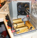
the dummy load is built into an old atx PSU case. uses 2 by 3.3 ohm tyco 50 watt power resistors per channel (6.6 ohms)
Fan is a 12V PC fan possibly the original? Its a while back I made this. Fan is powered by a bench PSU when in use, several connectors to aid linking up, will take 100+watts channel without overheating.
Attachments
Last edited:
- Status
- Not open for further replies.
- Home
- Amplifiers
- Solid State
- Impedance dropping with temp rise?