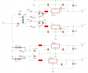
The voltage regulators in my Delta 1010's power supply are getting very hot because they are being fed an input voltage that's too high. The +/-15V regs are getting an input of about 25.5V and the +5V regs are getting an input of about 13V. I would like to reduce the input voltages by putting a resistor just before the input of the regs. Below is a schematic of the PSU with the additional resistors drawn in red. There's just one thing I'm not sure of. If you notice, there's a difference in the placement of the resistor for the input of U4 (+15V reg) versus the resistor for the input of U6 (+5V reg). The resistor for U4 looks like it's in parallel with the decoupling cap C15, whereas the resistor for U6 looks like it's in series with the decoupling cap C24. Which one of these is the proper or better placement, or does it matter -- will they work equally well?
Any help would be really appreciated. Thanks in advance! 🙂
Any help would be really appreciated. Thanks in advance! 🙂
Attachments
It depends on the circuit that is being powered on what I would do.
Adding resistors might reduce the heat but will it then cause the regulators to drop out ?
A simple answer might be too put larger heatsinks on the regulators.
When you say the regulators get hot, how hot ?
They can go over 100 degrees C and still be OK.
Silicon can go upto 150 degrees C before it dies although I wouldnt suggest going close to that.
It depends on the circuit that is being powered on what I would do.
Adding resistors might reduce the heat but will it then cause the regulators to drop out ?
A simple answer might be too put larger heatsinks on the regulators.
When you say the regulators get hot, how hot ?
They can go over 100 degrees C and still be OK.
Silicon can go upto 150 degrees C before it dies although I wouldnt suggest going close to that.
This is the power supply of an audio interface (soundcard with breakout box for recording studios) that has 8 balanced analog inputs and outputs, S/PDIF input and output, word clock input and output, and MIDI input and output. I use all of the I/O except the word clock. I use up to 6 analog inputs and outputs simultaneously, together with S/PDIF and MIDI.
Isn't the optimum input voltage for regulators the output voltage plus 3 volts, and any input voltage in excess of that is dissipated as heat? I would like to bring down the input voltage of the +/-15V regs from 25.5V to 18V, and the input voltage of the +5V regs from 13V to 8V.
I have already put additional large heat sinks on the +/-15V regs. Even with that they are still hot. The -15V reg is getting the hottest with a temp of 72.5C. The +15V reg is 60.2C. Both temps were measured by placing the temp probe on the heat sink for 40 secs. I also wonder why the -15V reg temp is a lot (12C) higher than the +15V reg.
Do you think that, in addition to putting the resistors, replacing the regulators with low drop-out type will also help?
Last edited:
The 3 volts across a regulator is the drop out voltage.
Any less than 3 volts and you wont get the right voltage out.
You need some headroom for when more or less power is being used by the system.
Any less than 3 volts and you wont get the right voltage out.
You need some headroom for when more or less power is being used by the system.
But the input voltages are really too high, aren't they? I think the regs need only 18V and 8V to function properly. 25.5V and 13V are way too much.
Back to my original question, without considering other things but just looking at the question from a proper circuit design standpoint, which one of those resistor positions is the proper or better placement, or does it matter -- will they work equally well?
Thanks! 🙂
Back to my original question, without considering other things but just looking at the question from a proper circuit design standpoint, which one of those resistor positions is the proper or better placement, or does it matter -- will they work equally well?
Thanks! 🙂
A LM7815 is rated to 125deg C . 60 to 70 deg should be OK.
I recently had a problem with a 15V reguator overheating, it had melted the solder and lifted the tracks off the PCB! Adding a bigger heatsink stopped it from going into thermal shutdown😱
Due to the nature of this power supply being a voltage doubler for the 15 - 0 - 15 supplies it has very poor regulation. A voltage reduction from 9V AC to 7.5V AC would cause a dropout. I would say that the high voltage reduction across the regulators ensures correct operation of the PSU in all conditions.
A LM7815 is rated to 125deg C . 60 to 70 deg should be OK.
I recently had a problem with a 15V reguator overheating, it had melted the solder and lifted the tracks off the PCB! Adding a bigger heatsink stopped it from going into thermal shutdown😱
Due to the nature of this power supply being a voltage doubler for the 15 - 0 - 15 supplies it has very poor regulation. A voltage reduction from 9V AC to 7.5V AC would cause a dropout. I would say that the high voltage reduction across the regulators ensures correct operation of the PSU in all conditions.
The maximum temp of 125C is for the internal junction temp, but the temp I measured was on the large heat sink that I added. If it's 72.5C outside, you can just imagine how hot it is inside! Maybe it's approaching the max inside already?
One side effect of the heat is that the smoothing caps are affected and are deteriorating fast. I put in new smoothing caps last week and got very clean THD+Noise graphs in RMAA. But after subjecting the unit to 14 hours burn-in, the graphs suddenly started to look bad. Now they are getting badder and badder each day that I turn on the unit and test with RMAA. I really need to reduce the temps!
You want the decoupling capacitor after the resistor to stabilize the voltage regulator.
U6 circuit.
U6 circuit.
You want the decoupling capacitor after the resistor to stabilize the voltage regulator.
U6 circuit.
Yes! That's what I'm talking about, the answer I've been waiting for. Thanks you so much!!

I have another question: Would it help the circuit to produce cleaner power if I replace the regulators with low drop-out types like LM2940 and LM2990? What are low drop-out regulators used for? In what situations are they preferable to use? What are their advantages and disadvantages versus non-LDO?
Thanks again! 🙂
Thanks again! 🙂
LDO's are useful when your input to output voltage is less than 3v. The Lm 78,79 series have bad noise performance. Many posts have been made on this site on how the Lm317,319 series of regulators out perform the '78,79 series. If you have the extra space to add the extra 2 resistors and capacitor they might be worth looking into.
My self - I just use a bunch of transistors and don't care about board space, unless someone complains.
My self - I just use a bunch of transistors and don't care about board space, unless someone complains.
Last edited:
LDO's also generally use mosefets as their pass transistors and have poorer performance at high frequency than their BJT counterparts (due to their gate capacitance). Although neither one are very good over 1KHZ.
Last edited:
LDO's are useful when your input to output voltage is less than 3v. The Lm 78,79 series have bad noise performance. Many posts have been made on this site on how the Lm317,319 series of regulators out perform the '78,79 series. If you have the extra space to add the extra 2 resistors and capacitor they might be worth looking into.
My self - I just use a bunch of transistors and don't care about board space, unless someone complains.
Input to output voltage considerations aside, do LDO's offer any better noise performance than LM78/79 series?
I will be using 2-watt resistors. The traces I need to cut are on the underside of the board. This is where the resistors will be soldered. I'm foreseeing a problem in that the resistors will be big and may not fit as there is not enough clearance between the underside of the board and the chassis. One solution to this problem is to place the resistors on the side (outside) of the board where there is a lot of clearance. However, this will require very long leads running from the resistors to their solder points on the board. My question is, will these long leads cause an inductance issue or act as an antenna to attract EMI/RFI noise? Is my only choice to cut out portions of the chassis to make room for the resistors? 😱
The clearance from the underside of the board to the chassis is 3.5mm. I would appreciate any recommendations for 2-watt resistors in a smaller size - 3.5mm or less in diameter or thickness. Those are what I need to not have to deal with this problem.
Thanks! 🙂
The clearance from the underside of the board to the chassis is 3.5mm. I would appreciate any recommendations for 2-watt resistors in a smaller size - 3.5mm or less in diameter or thickness. Those are what I need to not have to deal with this problem.
Thanks! 🙂
Last edited:
- Status
- Not open for further replies.
- Home
- Amplifiers
- Solid State
- Proper placement of additional resistors in Delta 1010 PSU?