I have found the 10M45S to vary in current about ±10% with a given resistance in the current adjust position. Since I want, in my present implementation, about 9 - 10mA draw from the CCS (4.5 - 5mA per tube in a diff-amp), and this equates to a little less than 300Ω, I use a 240 - 250Ω fixed resistor in series with a 100Ω 12-turn little pot, and dial those suckers right in using the voltage drop across the 43K plate load resistance, which is the biggest resistance in the subcircuit.
Yes, they vary a little, but ±10% is actually ridiculously tight for sand. Most transistors are considered to be within spec if their Beta (similar to Mu in a tube) is between half and twice stated nominal.
Aloha,
Poinz
AudioTropic
Yes, they vary a little, but ±10% is actually ridiculously tight for sand. Most transistors are considered to be within spec if their Beta (similar to Mu in a tube) is between half and twice stated nominal.
Aloha,
Poinz
AudioTropic
FWIW, my standard practice is to match or set anode voltage by circuit goal and let the current be what it is according to the tube as long as it's within reasonable range. If the 2 sections are matched within 20% in terms of current it should be plenty close for most uses. If you need it closer than this a distortion analyzer would be a good tool.
I was thinking along the same lines; but then again for power triodes we do have the option to set bias currents to match both sides when the tube ages. Doesn't this contradict?
I have found the 10M45S to vary in current about ±10% with a given resistance in the current adjust position.
Since I'm getting 239ohms and 272ohms respectively, doing the math, variations (assuming triodes are also slightly mismatched) is 12-13% which quite corresponds with your experience of 10% variations - GREAT, that's comforting to know.
Since I want, in my present implementation, about 9 - 10mA draw from the CCS (4.5 - 5mA per tube in a diff-amp), and this equates to a little less than 300Ω, I use a 240 - 250Ω fixed resistor in series with a 100Ω 12-turn little pot, and dial those suckers right in using the voltage drop across the 43K plate load resistance, which is the biggest resistance in the subcircuit.
I was thinking hard whether to leave those multiturn BOURNS trimpot in the circuit once dialled in. Does yours get hot to touch?
I see that you don't use the entire trimpot to take the load, and you insert a 240-250ohms fixed resistor to take the beating and then the trimpot to fine tune. But what's that 43K plate load resistance doing the path of the CCS? Shouldn't the CCS be connected directly to the plate?
In an LTP, the current source is in a common leg of both cathodes. Each anode has it's own plate resistor.
Optocouplers are good if you can get 600% tolerance on them. eg CTR = 50-300%
Optocouplers are good if you can get 600% tolerance on them. eg CTR = 50-300%
Yes, I'm only using 30-50Ω worth of the pot. I picked one that had a higher power rating, the Vishay CT94P series. I like having it in there. I can reach in with a screwdriver and change the OP of the front end tubes and hear what I can hear. Fun with 'lectricity.
Poinz
Poinz
I have found the 10M45S to vary in current about ±10% with a given resistance in the current adjust position.
My findings generally agree with yours. However, in the last batch I used, I got seven in a row within 2% ! 🙂
My findings generally agree with yours. However, in the last batch I used, I got seven in a row within 2% ! 🙂
Do you use a trimpot to tune the current and let it remain in the circuit?
Do you use a trimpot to tune the current and let it remain in the circuit?
Sure do - I use bourns cermet 10 turn, and have never had any issues. Current is set out of circuit using a high voltage bench supply and a current sense resistor.
I was thinking along the same lines; but then again for power triodes we do have the option to set bias currents to match both sides when the tube ages. Doesn't this contradict?
Matching voltage on the LTP driver sided makes sense to balance the voltage swing of the driver.
Matching idle current in the output stage makes sense for balancing current in the OPT.
Matching the driver tubes so the current is the same at == plate voltage may result in better dynamic matching, but it's not a guarantee.
Matching the output tubes so the bias voltage is the same at == plate current may likewise result in better dynamic matching.
I don't find any contradiction in this approach. all things are compromise.
Cheers,
Michael
PS When you measure voltage across Rset, do you find that the currents are balanced or not? i.e. is your mismatch due to tubes, MOSFETS, or both?
PS When you measure voltage across Rset, do you find that the currents are balanced or not? i.e. is your mismatch due to tubes, MOSFETS, or both?
I re-adjusted the trimpots tonight just to ensure the anode voltages are matching properly again as the right side is slightly off. I think the trimpots need another series resistor of perhaps 200 ohms to take the load as they are heating up a bit.
You can see in the pic attached.
Bloody hell this is an MIC amplifier, I just noticed that the left and right V supplies to the IXYS anode are not matched (267V and 278V respectively).
Trimpots are at 228ohms and 308ohms respectively.
Voltage across trimpots are 3.2V and 3.3V respectively.
Cathode LED stands at 2.0V on both sides.
Output voltages are 99.5V and 99.6V respectively.
Attachments
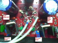
Ip = 14.03mA and 10.7mA respectively.
Indication of quite a large mismatch between the two sections of your dual triode.
Better IMHO to match the currents than the plate voltages as this will assure that the transconductances are close, this should also result in the voltages feeding the IXYs devices being similar if the dropping resistors used ahead of them are the same value.
Ip = 14.03mA and 10.7mA respectively.
Indication of quite a large mismatch between the two sections of your dual triode.
Better IMHO to match the currents than the plate voltages as this will assure that the transconductances are close, this should also result in the voltages feeding the IXYs devices being similar if the dropping resistors used ahead of them are the same value.
When a triode looses some life, does it make its tube curves more steep? Logically that would be the case, as I would need to pump in higher currents (a theoretical horzontal straight line on the tube graph and it climbs higher in the charts) just to compensate for a loss in anode voltage for a given cathode voltage.
Irregardless, whether matching anode voltage or currents, if the tubes are ill matched, wouldn't the gain be affected, hence affecting channel balance?
Normally as the tube ages emission falls, plate current drops, and plate voltage then increases (with a resistive load).. Using a CCS forces the plate voltage to increase as the tube ages in order to maintain the set current.
Just adjust your CCS for the same plate current and the gain between sections will match very closely as the effective transconductance will then be relatively closely matched - that is the whole point of using a CCS in the first place. Set for same plate current, not same plate voltage.
Hope this helps.
Excellent help thanks!
Normally as the tube ages emission falls, plate current drops, and plate voltage then increases (with a resistive load).. Using a CCS forces the plate voltage to increase as the tube ages in order to maintain the set current.
Just adjust your CCS for the same plate current and the gain between sections will match very closely as the effective transconductance will then be relatively closely matched - that is the whole point of using a CCS in the first place. Set for same plate current, not same plate voltage.
Hope this helps.
There is I believe more than one reason to use a CCS, the main one for me being high AC impedance. I'd just as soon use a gyrator and fix the plate voltage in the first place, i.e. low DC impedance and high AC but to each their own. Some circuits really benefit from the current limiting effect of the CCS.
Being a triode, the mu will probably be pretty stable no matter how you set things. I haven't noticed any significant differences in gain over the normal spread in triodes.
Anyhoo, setting the same standing current will only result in ~10V difference in plate voltage between your mismatched 6922 sections. No big deal
Cheers,
Michael
I have noticed rise in hiss levels with Mosfet or BJT anode CCS in some tubes, like 6V6 (trioded) & 12B4 for same current setting and voltage point as with a resistor. Hiss rise beyond the gain difference because of full mu exploitation when CCSed. Is this something noticed by others here too?
No, but the first thing I'd do is check for oscillations. Never had any kind of noise issue with discrete MOSFET or bipolar cascode CCS, in fact, quite the opposite.
Weird because there was no hint of dense wide band comb in the noise floor of FFT. Which is a sure sign of oscillation.
P.S. Another thing is that maybe other more suitable bias points should be used with a CCS than what was OK with a resistive anode.
P.S. Another thing is that maybe other more suitable bias points should be used with a CCS than what was OK with a resistive anode.
Hello Will and All,
If this is a science project, set it up as one.
A couple of suggestions;
Stick a 1000R resistor upstream of both sides of your test setup. Measure the voltage across the resistor and you have a direct reading of the current through each side. The 1K R can come out later, it is a current measurement tool.
Where the trim resistors are installed place a 1% resistor that is near the average cold reading of the trim resistors.
Now you can do close to precise current measurement and get rid of that damn trim pot for the final product. (Cold measurement of the trim pots vs actual in circuit values may not be even close.)
I bet you will surprised at how close things are even with unverified matching of leds, triodes and the like.
BTW Plus minus 3.8% was not that far off to start with.
DT
All Just for Fun!
Weird because there was no hint of dense wide band comb in the noise floor of FFT. Which is a sure sign of oscillation.
P.S. Another thing is that maybe other more suitable bias points should be used with a CCS than what was OK with a resistive anode.
What does the increased noise (hiss) look like on the FFT?
FFT front end capture is what? computer sound card, AP analyzer, wideband spectrum analyzer? It might be missing MHz ocsillation entirely but if you hear something it should show up on the FFT as something.
Check with a 20MHz or better (200MHz) oscilloscope. Audible noise should be visible as something.
There's no reason I can think of for the CCS to increase random noise more than a db or so (which should be more than made up for in gain), since the ENR of the circuit would be more a function of the triode's plate resistance or the pentode's load resistance.
To answer your question, I haven't noticed any increase in hiss when using a CCS in the anode or cathode circuit, or as a bias generator feeding constant current across a resistor, or in an LTP, or anywhere, I have built MHz oscillators out of CCS from time to time trying out weird ideas though.
Last edited:
- Status
- Not open for further replies.
- Home
- Amplifiers
- Tubes / Valves
- How badly matched are your IXYS10M45S ?