
 )
)
I was planning on using this for a couple of different projects I have on the go. One requires +/- 40V, the other +/- 65V. I doubt I will use 22mf caps, more than likely 10mf will suffice. I just thought that it wouldnt hurt to plan the boards to take the larger cans if required.
Here is a link to the board layout.
Board Layout
Here is a link to the board layout.
Board Layout
I completely agree. But the larger amp will reguire the bigger caps. I thought it would be easier to product 1 multi purpose board rather than 2 different ones. Especially as I will probably need to order sufficient to use a sheet of material, maybe 12 -15 boards.
I am thinking of selling a few of the excess to recoup some of the costs. A more "adaptable" board may possibly find a few extra takers.
I am thinking of selling a few of the excess to recoup some of the costs. A more "adaptable" board may possibly find a few extra takers.
I think you should choose a Caps which will optimize the design. choosing a very high value caps are not necessary for this kind of application.
What is the current rating you are thinking of offering? Calculate caps which will give lesser than specified ripple noise.
you can even use an inductor in series, still the cost will be lesser that using 22mF caps.
What is the current rating you are thinking of offering? Calculate caps which will give lesser than specified ripple noise.
you can even use an inductor in series, still the cost will be lesser that using 22mF caps.
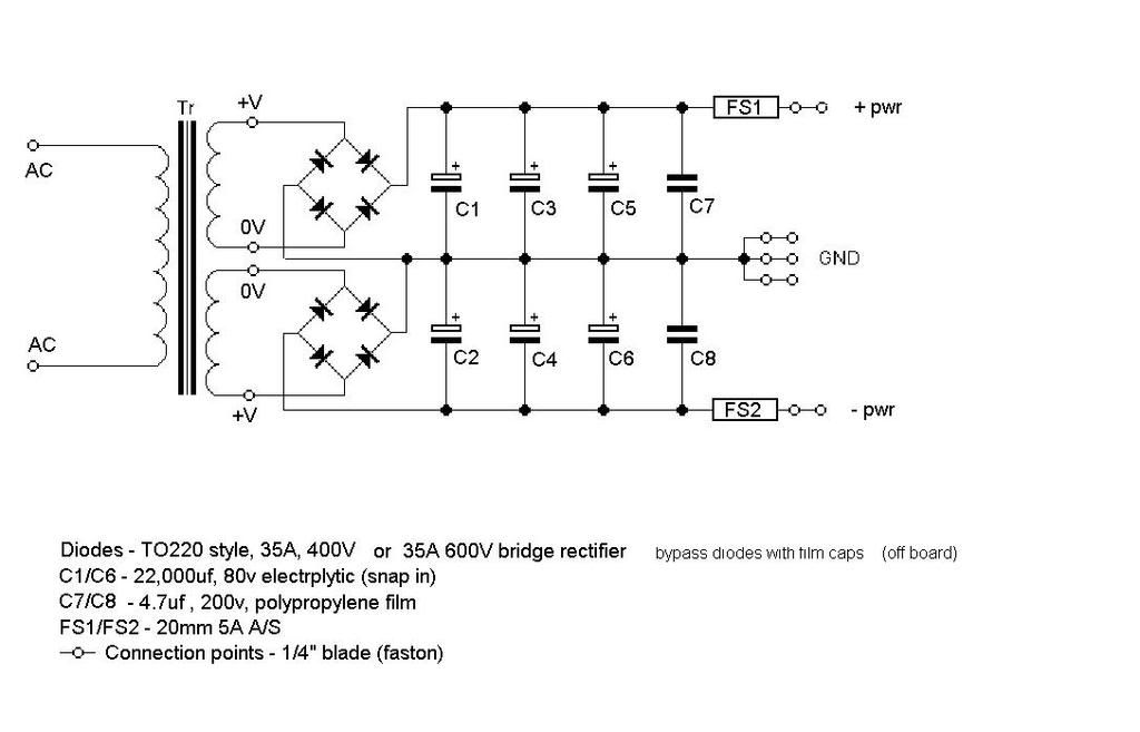
1. Use a single FWB. We've been through this before, you are literally burning away twice the voltage for absolutely no gain.
2. Way too much capacitance. You'll have poor power factor (0.5 or less!) and the possibility of induced ground loop anywhere near the power lines. If your circuit actually needs this little ripple, it's honestly a terrible circuit, reconsider your priorities.
3. Those poly caps won't do anything, even if the electrolytics have terrible ESR.
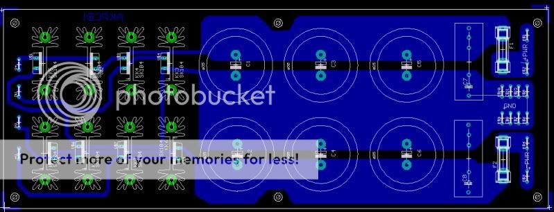
4. The layout shows hair thin AC tracks, was that intended to replace the fuses at the other end?")
Tim
2. Way too much capacitance. You'll have poor power factor (0.5 or less!) and the possibility of induced ground loop anywhere near the power lines. If your circuit actually needs this little ripple, it's honestly a terrible circuit, reconsider your priorities.
3. Those poly caps won't do anything, even if the electrolytics have terrible ESR.
4. The layout shows hair thin AC tracks, was that intended to replace the fuses at the other end?
Tim
Any critique welcome.
Don't use groundfill, use point to point (star earthing). Don't assume that because a schematic is drawn in a certain way, the layout must follow it.
I designed something similar to this a while ago, but as there was no interest and I can't afford to just have 1 or 2 made, it was abandoned. Let me know if you would like the Eagle files (it looks like that's what you're using).
Info post:
http://www.diyaudio.com/forums/chip-amps/147713-interest-check-15a-unreg-psu.html
Current revision:
http://www.diyaudio.com/forums/chip-amps/147713-interest-check-15a-unreg-psu.html#post1886187
Info post:
http://www.diyaudio.com/forums/chip-amps/147713-interest-check-15a-unreg-psu.html
Current revision:
http://www.diyaudio.com/forums/chip-amps/147713-interest-check-15a-unreg-psu.html#post1886187
Don't use groundfill, use point to point (star earthing).
Take no notice of what I said, groundfill is fine for power supplies, I've just spiced it. I do recommend though that in place of the big caps you use a few smaller ones in parallel, and put series resistors of lowish values between groups of them. This gives a worthwhile improvement to the HF ripple (where it matters more because the chipamp's PSRR is falling off with increasing frequency).
- Status
- This old topic is closed. If you want to reopen this topic, contact a moderator using the "Report Post" button.
- Home
- Amplifiers
- Power Supplies
- PSU Design Check Please