Hi have built Gary Pimm's 47 PP amp to revision 9 and want to rebuild the power supply to his stacked supply in rev. 10. I'm having trouble wrapping my head around how the ground reference works. Gary uses non-center-tapped transformers with Graetz bridge rectifiers. My transformer is a center tapped 375 -0 -375. Would there be any issue with using the center tap and full wave rectifier?
Thanks for any guidance you can give.
Thanks for any guidance you can give.
Maybe I'm the one who doesn't understand, but if you mean can you use just a fullwave tube rectifier and a center tapped transformer and build that PS, the answer is no. You need some technique to derive 2 rails, so at the very least you need to use a Graetz bridge with your fullwave rectifier and center tap.
Hmmm.. I thought that for a Graetz bridge (like a fullwave ss rectifier) one would normally not connect the CT, but I guess being able to derive the 2 rails is the crux of my confusion.
If I did the Graetz bridge with FW rectifier and CT, wouldn't my output voltage be way too high?
Thanks!
If I did the Graetz bridge with FW rectifier and CT, wouldn't my output voltage be way too high?
Thanks!
If I did the Graetz bridge with FW rectifier and CT, wouldn't my output voltage be way too high?
If you look at Pete's supply that you are trying to build, the output is 442V + 35V = 477V across both rails. Of course, your bridge stage actually needs to be higher than that since you need some voltage headroom for what is burned off as heat in the CCS and resistors.
You can't just use a FW tube rectifier, look at the rest of the circuit, it needs 2 rails to work.
An externally hosted image should be here but it was not working when we last tested it.
Thanks for the explanation, leadbelly. The concepts are starting to sink in. I'll go with Graetz bridge and no CT connected as per Gary's schematic.
Thanks for the explanation, leadbelly. The concepts are starting to sink in. I'll go with Graetz bridge and no CT connected as per Gary's schematic.
That of course will work, but if you want to go ahead and use your CT to avoid extra components, that is still a worthwhile goal, as others have already said. Maybe you should tell us more about what you were intending to do? You have this power trans that you mentioned. Do you have a tube rectifier on hand? Were you planning to use solid state rectifiers? Some more info would be a great help.
Wow, thanks for your persistence with helping me to figure this out!
OK, I have built the power supply for Gary Pimm's PP 47 almost exactly as drawn (I used a separate 25 v transformer for the driver cathode ccs). My PT is an old Thordarson 375 -0 375. My current HV supply consists of FW CT secondaries to 12ax4 damper diodes to 1.5uf cap to 7.5H choke to 30uf cap. Output voltage is ~330. What I'm trying to accomplish is to use this transformer to construct the stacked supply of Gary's rev 10.
OK, I have built the power supply for Gary Pimm's PP 47 almost exactly as drawn (I used a separate 25 v transformer for the driver cathode ccs). My PT is an old Thordarson 375 -0 375. My current HV supply consists of FW CT secondaries to 12ax4 damper diodes to 1.5uf cap to 7.5H choke to 30uf cap. Output voltage is ~330. What I'm trying to accomplish is to use this transformer to construct the stacked supply of Gary's rev 10.
Sorry to leave you hanging, I thought for sure somebody else would pipe up.
If you want, you can try to build the stacked supply with the components you have. You can make a hybrid bridge with the 12AX4s and SS rectifiers. How this would look is: the top rail would be connected to the cathodes of the 12AX4's, the middle rail is connected to the CT, and the bottom rail is connected to the anodes of the SS rectifiers. Be warned that there might be some tweaking required since your voltages will be slightly different, and you will certainly need to play with the dropping resistor to get that VR tube to fire and regulate properly. I would recommend that you model this in PSUDII. The program might seem confusing at first, but becomes so easy to use after you get past the 1st hurdle.
If you want, you can try to build the stacked supply with the components you have. You can make a hybrid bridge with the 12AX4s and SS rectifiers. How this would look is: the top rail would be connected to the cathodes of the 12AX4's, the middle rail is connected to the CT, and the bottom rail is connected to the anodes of the SS rectifiers. Be warned that there might be some tweaking required since your voltages will be slightly different, and you will certainly need to play with the dropping resistor to get that VR tube to fire and regulate properly. I would recommend that you model this in PSUDII. The program might seem confusing at first, but becomes so easy to use after you get past the 1st hurdle.
Hi leadbelly,
Thanks for this. Using the middle rail for the CT makes perfect sense.
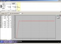
I've modeled quite a number of conventional PSs in PSUDII, so I'm comfortable with the program. I assume I would model the entire 477v range? What would be the best rectifier model to simulate a graetz bridge?
I'm planning on ordering a bunch of small to medium value caps to tweak the cLC filters and trying different values for the VR dropping resistors.
Thanks again!
Thanks for this. Using the middle rail for the CT makes perfect sense.
I've modeled quite a number of conventional PSs in PSUDII, so I'm comfortable with the program. I assume I would model the entire 477v range? What would be the best rectifier model to simulate a graetz bridge?
I'm planning on ordering a bunch of small to medium value caps to tweak the cLC filters and trying different values for the VR dropping resistors.
Thanks again!
Attachments
Your schematic isn't quite right: get rid of the 6AX4s and UF4007 and caps in the middle, and just leave the 6AX4s and UF4007 at the top and bottom respectively.
Sorry, I can't give you a more detailed answer about PSUDII right now because I can't run it here at work; I'll get back to you later if nobody else does.
Sorry, I can't give you a more detailed answer about PSUDII right now because I can't run it here at work; I'll get back to you later if nobody else does.
Getting close: delete the connection from the bottom of the transformer winding to the middle rail, and instead connect the bottom of the transformer winding to the bottom 6AX4 and UF4007. The top 6AX4 and UF4007 are already connected to the top of the transformer winding correctly.
- Status
- Not open for further replies.
- Home
- Amplifiers
- Tubes / Valves
- Question about stacked pawer supplies