Thanks, bearing in mind it was only a knock up from my scrap box, its sounding really good.
Very quiet with a Denon DL103, and very smooth, but detailed, dynamic and natural sounding🙂
Very quiet with a Denon DL103, and very smooth, but detailed, dynamic and natural sounding🙂
Did you try self bias with unbypassed cathode on 2nd stage? You shouldn't lose any significant gain by doing so and you could lose the battery in the grid. I favour battery grid bias but only when needed and in this case, you might not.
cheers,
Stephen
cheers,
Stephen
H Stephen,
Thanks for the sugestion, no i didnt try that, there is plenty of gain, so as you say loseing the grid bias battery in favour of a cathode reistor is probably a very good idea. I shall try it.
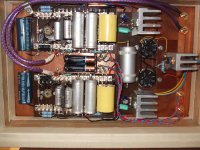
Heres a pic of the thing, as i say it was quickly constructed from parts i had on hand, you will notice the blown electrolytic cap i snipped out from the heater regulator! WOOps i put it in the wrong way round.
Despite the makeshift prototype construction, it sounds supriseingly good, and no hum.
Maybe it would be worth rebuilding, with better components/layout. and perhaps seperate VR tubes/CCs for each channel.
Thanks for the sugestion, no i didnt try that, there is plenty of gain, so as you say loseing the grid bias battery in favour of a cathode reistor is probably a very good idea. I shall try it.
Heres a pic of the thing, as i say it was quickly constructed from parts i had on hand, you will notice the blown electrolytic cap i snipped out from the heater regulator! WOOps i put it in the wrong way round.
Despite the makeshift prototype construction, it sounds supriseingly good, and no hum.
Maybe it would be worth rebuilding, with better components/layout. and perhaps seperate VR tubes/CCs for each channel.
Attachments
Qute nice indeed. I would replace the shunt portion of the regulator with "Salas simplistic" - less noise and better sound.
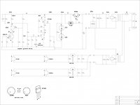
Hi, The preamp was built to try out the hybrid fet/valve cascode, and i have to say i am impressed.
Yesterday i tried cathode bias resistors in place of the grid bias batterys, i didnt notice a drop in gain, though perhaps the bass seeemed a little less tight, going to listen to it a while longer, not a huge difference at all though.
And any simplification is always welcome.🙂
I did consider a more complex shunt regulator, such the the very highly regarded "Salas simplistic" shunt reg, but i had the VR tubes on hand, and was curious as to how they would perform in a sensitive high gain phono amp.
Certainly from a noise perspective, they appear invisible.
I think this is a far as i wish to take this project at the moment as i have an all valve mc compatable preamp on the drawing board, something i have been considering for a long time.
Velvetsunrise,
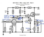
Your implementation of a JFET/6GK5 cascode is of considerable interest to me. I badly want to do something along the same lines. I'm inclined to keep your 1st gain block and EQ network intact. However, I'll stick with the grid leak biased 2nd gain block in the attached tweaked version of RCA's venerable design.
Your implementation of a JFET/6GK5 cascode is of considerable interest to me. I badly want to do something along the same lines. I'm inclined to keep your 1st gain block and EQ network intact. However, I'll stick with the grid leak biased 2nd gain block in the attached tweaked version of RCA's venerable design.
Attachments
I think this is a far as i wish to take this project at the moment
Your decision of course. After replacing the reg tubes with Salas shunt i have sworn to never ever use such tubes in my designs. I also use a cascoded CCS - another nice improvement.
Eli D,
Try the front end it does sound very good. Very smooth and very dynamic. I used BL grade matched IDSS Jfets, not measured the gain, but in my system its about perfect for a denon DL103.
One thing i may try, is, place the eq network directly accross the first stage anode load resistor, removeing the build out resistor, or, alternativly, split the RIAA eq by placeing a cap across the first stage Anode load resistor to form the 75us time constant, around 3n2 i think.
The remaining time constants could perhaps be placed at the grid off the upper mu stage valve, or the anode of the lower mu stage valve, not seen this arrangement before, not sure if this would work but will give it a try.
analog_sa.
Thanks for your suggestions, your considerable experience is taken on board.
I do intend to try something similar to the salas shunt reg with my planned all valve mc pre, as i am sure, as you say, it will give much improved performance over the VR tubes.
One thing i may try, is, place the eq network directly accross the first stage anode load resistor, removeing the build out resistor, or, alternativly, split the RIAA eq by placeing a cap across the first stage Anode load resistor to form the 75us time constant, around 3n2 i think.
I ran a cascode input stage very similar to this one in my old phono preamp. The RIAA configuration you have now is much better than the one you're proposing- the tube has a nice, straight loadline which is not too demanding at HF. In your proposal, the loadline becomes elliptical and gets more vertical at higher frequencies (i.e., higher distortion).
The best upgrade you can do is a better power supply. Cascodes have absolutely pitiful power supply rejection so need all the help they can get.
Thanks for that SY, i think i will call it a day with this one, at least for now!
And, concentrate my efforts into something, with better Powersuply rejection along the lines of your excellent His Masters Noise preamp.
Great read by the way🙂
Cheers.
And, concentrate my efforts into something, with better Powersuply rejection along the lines of your excellent His Masters Noise preamp.
Great read by the way🙂
Cheers.
VERY intersting design, and also very clever.
I'd have some questions...
Do the diodes on the adj leg of the regulators make them put out 6.3V? Any reason why no LM317 was used?
Are the RIAA caps Russian teflon types? How many did it take to find matching capacitors?
And please, could we see some pictures from the top, preferably with glowing tubes?
Hi,
The diodes add aproximatley 1.25v to the 5V regulator output. A 317 is preferable, but i had the 5volt regs handy and doing nothing, they appear to give adequatley low ripple and low noise.
Yes the Eq caps are 10n russian teflons, 3 in parrallel to form the 30n. Out of a batch of 20caps i was able to match to better than 1%. I have not measured the riaa acuracy, but i cannot detect any gross audible inacuracy.
As i stated previously, i built this just to try out the jfet/valve cascode, and the effectivness of a simple VR tube regulator, with what parts i had on hand.
Given that the cascode has zero power supply rejection, i can conclude that the VR tubes do a pretty good job of reducing ripple, leaving a quiet power supply, although i accept as pointed out by more experienced builders, it probably can be improved upon considerably with a salas type shunt.
As to the Jfet/valve cascode, its certainly a great way to get large amounts of gain and low noise from a simple stage, and to my ears it doesnt sound solid state, or tubey for that matter! just neutral.
Before i go any further with a jfet/tube cascode based pre, i wish to try out a high gm triode such as the 6C45p, as rumor has it with carefull layout, and correct choice of operating point, it can be made quiet enough (just) for medium output moving coils straight in.😱
I need to try this approach and find out for myself if this is true,
We shall see.

A curious idea for sure and nice prototype, but there's one thing that worries me. Directly connecting a moving coil cartridge to active circuit elements is risky. An MC, with it's very fine and delicate wire windings, could find itself in danger of burnout if the FET gate (or tube grid) develops excessive leakage current. Without the isolation of a transformer, capacitor or even a series resistor, which could be fairly high since the signal current is only picoamps, I would not put my MCs in that peril. And I still use a DL-103D that can't be replaced anymore. I've seen this happen to tape heads BTW. Just food for thought.
Hi Eli!
I was not here for quite some time, and here I start with a critical question ...
I see in characteristic tables that unless a 'grid leak' biased stage is preceded by a very low impedance driver (and of course depending on the tube), the distortion could be higher than with cathode bias. I have not measured that for myself, though. Any comments?
Hi Eli!
I was not here for quite some time, and here I start with a critical question ...
I see in characteristic tables that unless a 'grid leak' biased stage is preceded by a very low impedance driver (and of course depending on the tube), the distortion could be higher than with cathode bias. I have not measured that for myself, though. Any comments?
Give credit to Thorsten Loesch for making the grid leak bias suggestion. The very large grid leak resistor lightly loads the EQ network, which improves bass extension. I can't say, 1 way or the other, about distortion. What I can say is that those who have built the tweaked RCA circuit have been pleased.
- Status
- Not open for further replies.
- Home
- Amplifiers
- Tubes / Valves
- Fet 6Gk5 ECC88 mc phono stage