Hi everybody!
I was wondering if its possible to build a power amp based on the typical qsc topology with floating power supply, but using a discrete circuit, eg. LTP instead of the opamp driving the output transistors.
has anybody done this so far?
if you dont know what i mean, you can look at the qsc 1080 schematic. its so far the simplest amp i found using this topology.
thanks in advance
Yes, of course. You don't need an opamp, just an amp with inv and non-inv inputs for feedback arrangements. And that amp two inputs need not to be of the LTP stage (balanced). Opamp is used for more gain in open loop, which is not a requirement for the circuit to perform well.
QSC use drains/collectors connected to ground, so this is suitable for many typical transistors/V-MOS, since it will have heatsinks at zero potential.
For L-MOS (where the sources are on the case), it makes sense to ground the sources.
Plenty of ideas for inquiring mind can be found here:
DNFB 2SJ200/2SK1529 overturned power amplifier
and in Hafler pat. US4467288
input stage supply
You will need a seperate power supply for the input stage, one which does not swing with the audio. The qcs type kept charge on a pair capacitors by using the output swing as bootstrap, this is why shorting the amp made the signal go down.
You will need a seperate power supply for the input stage, one which does not swing with the audio. The qcs type kept charge on a pair capacitors by using the output swing as bootstrap, this is why shorting the amp made the signal go down.
interesting topology.
here two URL's regarded this amp:
Hafler 9505
Hafler - Home
also Altec and Harrison works with grounded collector resp. grounded source in their output stage, but with integrated OP-AMP driver solution:
http://www.diyaudio.com/forums/soli...t-complementary-ab-bipolar-amplifiers-11.html (post #102)
http://www.diyaudio.com/forums/solid-state/147392-harrison-type-k4000-k-4000-mkii-2x1000w-4ohm.html
Attachments
Last edited:
its 2010 - the "op amp" doesn't have to be NE5534
Dr Ed Cherry advocated for CE output stages, pointing out that taking all of the V gain in the output Q lets the input circuitry run at low Vsupply allowing faster Q
but the question today would be why avoid the op amp input and driver when you could use some of the past decade's better op amps?
except for lowest noise with exotic source impedance today's best op amps built on fast complementary isolated processes have better internal Q parameters than you see in discrete diy audio amp circuits here
also skilled design teams at Analog, BB/TI, Linear, National, backed with deep institutional knowledge have considerably upped op amp circuit topology for low distortion at high frequency performance over the past decade due to A/DSL performance demands
a composite multiloop op amp circuit with a modern low noise precision op amp input and CFA A/DSL driver op amp output should easily outperform any discrete diy hobbyist (and at this point any audio pro discrete design) circuit with consumer line level input
Last edited:
Er, you do NOT need a separate power supply for the input stage - I have a standard LTP and VAS running off 15V zener rails from a QSC style design. The "bootstrap" capacitor is to provide drive limiting during overload conditions.
Hafler patent for LTP interface (9505 topology) is US5936467.
Amazing! Only eleven years old:
Dynamically invariant AB linear operation amplifier
Yes, but for another problem I don't find a solution: the oscillation both in real live and by simulation (see attachement). Who have an idea, where I must introduce the compensation caps?Er, you do NOT need a separate power supply for the input stage
Attachments
Last edited:
qsc type circuit stability
What makes these circuits a little tricky is the op amp in a global feedback loop. The op amp used must allow the loop to be closed in a short time. A high slew rate op amp may still have a long propagation delay. A transistor input stage is often easier for diy for this reason. A 2n5550 ltp has a very short delay, and you have access to everything for compensation. Qsc modified thier version over the years, so check a newer ('90s or later) schemo. Some compensation points : 10pf across feedback resistor, or 47 to 100 pf across c-b of drivers. It all depends on the op amps ,drivers and outputs used. In general, the sooner global feedback closes the loop, the better. So compensation caps should only reduce gain spikes, but not slow down the amp much.
What makes these circuits a little tricky is the op amp in a global feedback loop. The op amp used must allow the loop to be closed in a short time. A high slew rate op amp may still have a long propagation delay. A transistor input stage is often easier for diy for this reason. A 2n5550 ltp has a very short delay, and you have access to everything for compensation. Qsc modified thier version over the years, so check a newer ('90s or later) schemo. Some compensation points : 10pf across feedback resistor, or 47 to 100 pf across c-b of drivers. It all depends on the op amps ,drivers and outputs used. In general, the sooner global feedback closes the loop, the better. So compensation caps should only reduce gain spikes, but not slow down the amp much.
I had the occasion to compare a QSC1300 against an home made
amplifier using mosfets.
As sound source, we used a fender jazzbass connected to
a SVT ampeg preamp.
A friend which is a professional bassist did play using these
setings.
The QSC amp was simply awfull , with hollow basses despite
being more powerfull than the modest diy mosfet amp...
amplifier using mosfets.
As sound source, we used a fender jazzbass connected to
a SVT ampeg preamp.
A friend which is a professional bassist did play using these
setings.
The QSC amp was simply awfull , with hollow basses despite
being more powerfull than the modest diy mosfet amp...
v gain in output stage
Another problem with using the output stage for voltage gain is that the output current modulates the open loop voltage gain.The hafler version of this idea used mosfets, so it had far less gain modulation artifacts. With a conventional vas and double or triple output stages, you have the benefit of seperating the voltage gain from current gain. A lot depends on your application, some designs which make for a good solid pa amp, are not the best for hi fi.
Another problem with using the output stage for voltage gain is that the output current modulates the open loop voltage gain.The hafler version of this idea used mosfets, so it had far less gain modulation artifacts. With a conventional vas and double or triple output stages, you have the benefit of seperating the voltage gain from current gain. A lot depends on your application, some designs which make for a good solid pa amp, are not the best for hi fi.
sorry for this mistake:interesting topology.
here two URL's regarded this amp:
Hafler 9505
Hafler - Home
also Altec and Harrison works with grounded collector resp. grounded source in their output stage, but with integrated OP-AMP driver solution:
http://www.diyaudio.com/forums/soli...t-complementary-ab-bipolar-amplifiers-11.html (post #102)
http://www.diyaudio.com/forums/solid-state/147392-harrison-type-k4000-k-4000-mkii-2x1000w-4ohm.html
I mean post #103 and not post #102 about
http://www.diyaudio.com/forums/soli...t-complementary-ab-bipolar-amplifiers-11.html
Yes, of course. You don't need an opamp, just an amp with inv and non-inv inputs for feedback arrangements. And that amp two inputs need not to be of the LTP stage (balanced). Opamp is used for more gain in open loop, which is not a requirement for the circuit to perform well.
QSC use drains/collectors connected to ground, so this is suitable for many typical transistors/V-MOS, since it will have heatsinks at zero potential.
For L-MOS (where the sources are on the case), it makes sense to ground the sources.
Plenty of ideas for inquiring mind can be found here:
DNFB 2SJ200/2SK1529 overturned power amplifier
and in Hafler pat. US4467288
are there any news concerning this topology (both commercial products and diy-projects) ?
are there any news concerning this topology (both commercial products and diy-projects) ?
I have been thinking about putting together a topology with grounded collector outputs and all discreet with no opamp in the loop.
I find this grounded collecteur topo very interesting. It avoids all the extra junctions and makes things much easier on the heatsink side. Plus it's funny to see the speakers connected at the middle point on the power supply...
Any schematics already done??
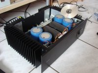
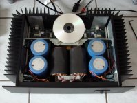
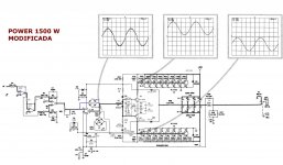
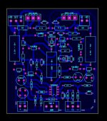
GROUNDED COLLECTOR QSC
Some qsc clones grounded collector many diyers have constructed these amps
warm regards
andrew lebon
Some qsc clones grounded collector many diyers have constructed these amps
warm regards
andrew lebon
Attachments
service manual byThe Crown PSA-2 has an opamp, but is not similar to the way QSC uses theirs.
http://www.crownaudio.com/media/pdf/legacy/psa2servicemanual1of7.pdf
unfortunately don't provide the schematic.
- Status
- Not open for further replies.
- Home
- Amplifiers
- Solid State
- QSC topology, but without opamp?