Nelson and ZenMod are two old & old-fashioned guys which don't understand modern trends (anymore)! 

....
The only answer I never got: how much is PSRR of the amplifier circuit.
Let's give me the answer by myself: Enough 🙂 ...
Precisely! 😀
BTW, it was very brave to show that, that... (oh god, it's hard even to type it), that speaker cabinet (there, I did it) 😉
man - I like it ...... so much , that I forgot to write :
Fugly!
that reminds me that I promised to my better/smarter/nameit half that she'll decide color of next spks for living room ;
I told her - "whatever color you choose , I'll accept even black .... "
WTF , I'll even glue wallpapers on it , if she wants

Fugly!
that reminds me that I promised to my better/smarter/nameit half that she'll decide color of next spks for living room ;
I told her - "whatever color you choose , I'll accept even black .... "
WTF , I'll even glue wallpapers on it , if she wants
man - I like it ...... so much , that I forgot to write :
Fugly!
that reminds me that I promised to my better/smarter/nameit half that she'll decide color of next spks for living room ;
I told her - "whatever color you choose , I'll accept even black .... "
WTF , I'll even glue wallpapers on it , if she wants
You have speakers ? .................. 😀
any pics of the amp itself?
Not yet, sorry.
I missed to make fotos. I about two weeks I will open it again to verify adjustments and to add a LED.
I will make a picture at this occasion.
Greetings
Frank, oh confused, Franz
You have speakers ? .................. 😀
Neuh, he always does the talking himself.
I see that when I wasn't looking, this thread broke a million
views.
Let me tell you, it's hard word sitting around pressing F5
all by yourself.
😎
views.
Let me tell you, it's hard word sitting around pressing F5
all by yourself.
😎
Hi
Almost there! 🙂
I biased both channels yesterday but could only do it by having one channel connected to the power supply at a time. When I connect both channels it causes the bulb tester to illuminate. I've tied both of the grounds together and have a CL60 in series to chassis safety earth. I'm using Cvillers power supply and amp PCBs
When the bulb illuminates the supply is only producing 5.4v per rail, not ~25vdc. I've obviously forgotten to do something simple.
Any suggestions?
Thanks
Last edited:
Hi Nelson
Congratulations for the million! (What do you mean with F5? Key or amplifier? Smile)
How is the feeling as a millionaire?
Maybe, soon I know it also: recently I made a funny video, already 750000 accesses during two months:
YouTube - Mama Bear, Björk, is trying to shake a baby bear from a tree in Bärenpark Bern
I heard, also Jay Leno showed this video in his talkshow.
Maybe you have a look at my desk:
Next project: a F5 for me, personally 🙂
BTW: there is a second similar Klein und Hummel enclosure under the desk. The trannies are also showing too high voltages (two times 40VAC and two times 57VAC) per tranny.
Nelson: could you possibly adapt the F5 circuit for higher rail voltages? This would open the window for many people to resurrect old PA amps!
It would be nice to build two 3 channel amps to drive my active 3-way setup.
Lets look.
Franz
Congratulations for the million! (What do you mean with F5? Key or amplifier? Smile)
How is the feeling as a millionaire?
Maybe, soon I know it also: recently I made a funny video, already 750000 accesses during two months:
YouTube - Mama Bear, Björk, is trying to shake a baby bear from a tree in Bärenpark Bern
I heard, also Jay Leno showed this video in his talkshow.
Maybe you have a look at my desk:
An externally hosted image should be here but it was not working when we last tested it.
Next project: a F5 for me, personally 🙂
BTW: there is a second similar Klein und Hummel enclosure under the desk. The trannies are also showing too high voltages (two times 40VAC and two times 57VAC) per tranny.
Nelson: could you possibly adapt the F5 circuit for higher rail voltages? This would open the window for many people to resurrect old PA amps!
It would be nice to build two 3 channel amps to drive my active 3-way setup.
Lets look.
Franz
Last edited:
Hi
Almost there! 🙂
I biased both channels yesterday but could only do it by having one channel connected to the power supply at a time. When I connect both channels it causes the bulb tester to illuminate. I've tied both of the grounds together and have a CL60 in series to chassis safety earth. I'm using Cvillers power supply and amp PCBs
When the bulb illuminates the supply is only producing 5.4v per rail, not ~25vdc. I've obviously forgotten to do something simple.
Any suggestions?
Thanks
if one channel is working good with one bulb in series with mains , then wire two paralleled bulbs for two channels
seems that increased current through bulb is choking mains voltage to xformer
Hi Nelson
......
Nelson: could you possibly adapt the F5 circuit for higher rail voltages? This would open the window for many people to resurrect old PA amps!
.......
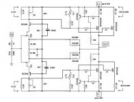
not exactly Nelson but ........
 ..........
 if you search - you'll find at least few versions of cascoded F5 - good for higher PSU voltages ;
find schematic , post and write what are your presumed PSU voltages
btw - that search will increase number of hits in thread , no doubt
if one channel is working good with one bulb in series with mains , then wire two paralleled bulbs for two channels
seems that increased current through bulb is choking mains voltage to xformer
Hi
I'm not sure I follow 😕
not exactly Nelson but ........ ..........
if you search - you'll find at least few versions of cascoded F5 - good for higher PSU voltages ;
find schematic , post and write what are your presumed PSU voltages
Ohh, interesting!
Sometimes, the world is turning too fast and I miss some things 😀
Search within this thread?
So I guess, when I use the 40VAC windings, I will get about 50VDC under load, possibly 52VDC per rail when I use one tranny per channel.
Any suggestions?
Franz
Last edited:
Hi
I'm not sure I follow 😕
I resumed that you're using "test bulb " as "fusing" device , in line with mains ?
just set all trimpots (two per channel) to zero ohms ; check that with ohmmeter
connect your "test bulb" as previously - one channel at a time and check voltages - is something smelling etc.
if everything is ok , connect both channels and fire da thing without testing bulb
bias it per million times explained procedure
enjoy
......
Any suggestions?
Franz
use the search button ........ or look down
( give me exact values of PSU voltage and I'll double check values for you )
Attachments
- Home
- Amplifiers
- Pass Labs
- F5 power amplifier