There is another way to do all of this of course and that is to string a potentiometer across the emitters of the output devices and then take the feedback from the wiper - continuous adjustment of the 'magic' resistor. I didn't try this though.
Yeah, the wiper contact might be the secret ingredient to modulate the feedback signal is just the right way. 🙂
regards
Gareth,
I like your 120K resistor. It's cool. Greg is probably right, but you can always force correct offset by varying input stage current.
Have you considered using two smaller outputs on the negative side, and one big output device on the positive side? A wacky three output devices, just for a laugh? This dissimilarity might happily create some odd order!
Hugh
If you stretch the pot across the resistors like said, offset may be nulled but you'll be amplifying odd harmonics instead of evens; the arrangement will be symmetric.
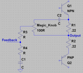
I suggest to put a cap in series with the Magic resistor, so that the actual feedback loop controls the offset. My thoughts for "variable magic" attached.
Also, I wonder what the effect would be to put some kind of filtering into this resistor. Say, filter out 2nd harmonics for bass or something...
- keantoken
Attachments
Last edited:
Member
Joined 2009
Paid Member
Yeah, the wiper contact might be the secret ingredient to modulate the feedback signal is just the right way. 🙂
just think how much we could sell them for 😎
Gareth,
I like your 120K resistor. It's cool. Greg is probably right, but you can always force correct offset by varying input stage current.
Have you considered using two smaller outputs on the negative side, and one big output device on the positive side? A wacky three output devices, just for a laugh? This dissimilarity might happily create some odd order!
That's a good suggestion. I've seen some designs with mixed outputs, such as Pavel's Power Follower and Broskies tube/FET hybrids and there are some triple power device outputs such as Graham Maynards GEM etc but I don't think I've seen anybody exploit properly the benefits of an asymmetric output structure in that way. It could create some very novel options !!!!
If you stretch the pot across the resistors like said, offset may be nulled but you'll be amplifying odd harmonics instead of evens; the arrangement will be symmetric.
I suggest to put a cap in series with the Magic resistor, so that the actual feedback loop controls the offset. My thoughts for "variable magic" attached.
Also, I wonder what the effect would be to put some kind of filtering into this resistor. Say, filter out 2nd harmonics for bass or something...
I actually simulated a few things before I settled on the simple resitor. I started off by making the output asymmetric by using different valued emitter resistors for the upper and lower devices. It's a nice trick because you can make this change without adding a feedback loop. I very nearly went this direction but decided to explore further because shifting the actual output away from the mid point appeared to increase slightly the odd harmonics.
I had thought the way that the asymmetric emitter resistors worked was to change the effective 'gain' of the output devices but I think it actually works by shifting the feedback point so that it is no longer at the half-way point between the emitters of the output devices. The potentiometer achieves the required result quite nicely and this is the better way of implementing the tubey effect in a variable manner without increasing odd harmonics. I didn't do this because I couldn't be bothered wiring up a pot. So the simple feedback resistor I used provides the asymmetric feedback but at the expense of having two feedback resistors.
The real benefit here is that you increase the even harmonics, especially H2, without increasing the odd harmonics. If you start off with a clean amplifier you can tune in the tubey sound. It's just beautiful !
You could introduce a capacitor in series with the magic feedback resistor, providing that you still have a dc feedback path from the regular feedback arrangement. I actually explored this R+C arrangement on TGM1 when I fed back some of the output to the top of the LTP to inject harmonics. The idea being that I wanted to avoid injecting harmonics at low frequencies so as not to soften up the bass.
Lots of things to play with here !
Last edited:
Bigun, are you up to making a new harmonic graph? I have some ideas on how to make it more informative...
- keantoken
- keantoken
Member
Joined 2009
Paid Member
My thoughts are:
1: Mark the AB transition point, IE where class A becomes AB. It would be informative to see where this lies in relation to the harmonics. (probably at about 2W, one output switching off is probably responsible for stopping the rise of 2nds)
2: X axis should be exponential, to conform to perceived loudness.
Hell, send me the LTSpice file and I'll do charts for everything... There are a few more dimensions I'd like to graph...
- keantoken
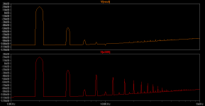
This graph illustrates the difference you would get between an NTP input and the resistor mod. I wonder if a bit of both might go a long way...
The actual values are not significant, obviously 20db of H2 is over the top... This just indicates the difference in type of profile that comes with each. Orange trace is NTP.
- keantoken
The actual values are not significant, obviously 20db of H2 is over the top... This just indicates the difference in type of profile that comes with each. Orange trace is NTP.
- keantoken
Attachments
Member
Joined 2009
Paid Member
That looks interesting - I think you need a fair bit of H2, it's a fairly benign harmonic. In fact your output looks 'too' clean, there needs to be some H3 too.... ?
What gets me is the dip in harmonics after H3 and then the gradual rise of higher order ones. Maybe it is better to have a straight line rather than a hump?
The second line is an FFT of the same simulation, taken from one of the output emitters. This is the profile that's injected into the feedback loop with the magic resistor, when actually implemented thirds might be stronger.
The top trace using the NTP, is from an amp with fairly high OLG; the NTP injects the H2 and even harmonics while the Rush pair (which does the actual feedback work) generates the H3, which is why H3 is so low. To decrease H3, OLG could be lowered, or we could deliberately imbalance the level shifters.
- keantoken
Hey Bigun, I've been interested in Symasym since I joined this forum. Look at this page with spectrum plots:
Symasym V5_2 review
- keantoken
Symasym V5_2 review
- keantoken
I just found this very interesting article:
Milbert Amplifiers, Most Musical Amplifiers
Sounds like exactly what we are looking for.
- keantoken
Milbert Amplifiers, Most Musical Amplifiers
Sounds like exactly what we are looking for.
- keantoken
It turns out that article was translated by our very own Jan Didden! I wish I could find a copy with pictures...
The article is discussed in this thread:
http://www.diyaudio.com/forums/solid-state/57995-many-faces-distortion-2.html#post666324
- keantoken
The article is discussed in this thread:
http://www.diyaudio.com/forums/solid-state/57995-many-faces-distortion-2.html#post666324
- keantoken
Member
Joined 2009
Paid Member
The symasym charts look very good. I've never heard this amp, but I've noticed it has a very good reputation on the forum.
Reminds me that we don't really need to be designing any new amplifiers, there are plenty of good designs ready to build if we want to.
Reminds me that we don't really need to be designing any new amplifiers, there are plenty of good designs ready to build if we want to.
The amp is nearly fully symmetric. Also notice he doesn't use Cdoms (he himself said he avoids Cdoms). So you may want to try playing with different types of compensation (I've done a lot of simulator tests, I can get you started).
The joy of this hobby to me for the moment is that it turns out there IS some unexplored territory, in the topological No Man's Land. There are many old ideas that failed, and haven't been repeated or fully explored since because of the stigma. But we know more now, and we have more tricks... Some of the esoteric options, such as stranger forms of compensation, and the NTP, are now possible.
But other than that... In a word, yes. It is not strange to think the best designs have already been built...
- keantoken
Are you talking about the symasym ? It has cdom (see first pix) as well as having the VAS loaded by an R/C network. Even Roenders RMI-fc100 ( a common base VAS/cascode precision version of the symasym ) uses a ground shunt CDOM.
OS
Definitely the most reliable , very accurate ... all my variants of the original have "cranked" away for over a year now. very adaptable for different semi's.The symasym charts look very good. I've never heard this amp, but I've noticed it has a very good reputation on the forum.
OS
Attachments
I'm not sure what qualifies a cap as a Cdom (so I apologize), but anyways he didn't use compensation in the conventional way.
- keantoken
- keantoken
How would you qualify it ? it might not be Cdom , but it It sets Cdom. In many schema's it is designated as Cdom..I'm not sure what qualifies a cap as a Cdom (so I apologize), but anyways he didn't use compensation in the conventional way.
- keantoken
Some old amps made with ancient silicon don't have miller comp. , because the slow Ft of the devices themselves set the compensation.
Audio Power Amplifier Design Handbook - Google Books
Miller cap = Cdom p. 263 amplifier handbook - D. self

or - Engineering 93 “Sweet Speakers”
miller effect spice page..
The symasym R/C compensation alters the primary Cdom and loads the voltage stage , I agree .. unconventional.
without the primary miller cap (100p), HF loop gain would be too high ... a dandy speaker blowing oscillator you would have !!

Last edited:
Good to see you here again ostripper, welcome back.
I have to agree with ostripper, that 100p looks like cdom to me too.
I have a challange for bigun and keantoken though.
You guys concentrate very much on the distortion profile of a amp but you are neglecting some facts. I would like to challange you to go and listen to couple different amps that I have some information about. I will just give the amps name and then you can tell me how you liked the different amps.
The idea being that I know what their harmonic profile is and Im wondering whether youll choose the best sounding ones as being always the one with your preferred spectrum.
I have surprised so many others with this test I think Ill catch you out with this test too. I think you guys will get a better perspective on how exactly you should look at these harmonic spectrums, keep in mind that a amp is just one link in a chain, ever think what the effect maybe of the source, cdplayers and preamp do have THD too Im sure you know.
- Status
- Not open for further replies.
- Home
- Amplifiers
- Solid State
- TGM amp goes 'tubey'