I'm thinking physics here. Why do you reach a point where an increase in grid voltage only only sucks major grid current but doesn't seem to decrease plate voltage/increase current?
Triodes and pentodes seem to saturate in much the same way, just triodes need a positive control grid to get there. What's the physical cause of this barrier that seemingly can't be crossed without melting something?
Triodes and pentodes seem to saturate in much the same way, just triodes need a positive control grid to get there. What's the physical cause of this barrier that seemingly can't be crossed without melting something?
The valve basically works when there is an electron flow from cathode to anode. This is regulated by the potential on the grid. The grid is normally biassed negative with respect to the the cathode, and repulses or impedes the electron flow from the cathode to the anode to a degree. In 'normal' operation an increase in grid voltage results in greater current flow from cathode to anode as the grid impedes the flow less.
As the control voltage swings more positive, and grid voltage approaches 0V WRT the cathode, the electrons are no longer repulsed by the grid, but are attracted to it, despite the potential on the grid being nowhere near that on the anode. Electrons which would normally pass the grid are diverted from the anode onto the grid, and grid current then flows, and the operation of the tube departs from what is considered 'normal' in audio applications.
w
IIRC. Oh, you can run with grid current in dual valve applications where one valve operates 'normally' while the other phase is drawing grid current. There's also class C, but we'll let that alone for the moment.
Last edited:
The "barrier" is due to the positive grid (G1 or G2) stealing cathode current.
In ordinary operation, plate resistance is due to electric field "leaking" through the grid wires. The shielding effect forces plate resistance to be much higher than a diode's, but it also allows control; tighter-spaced grid wires make higher mu, while loosely-spaced wires make lower Rp (more field leaks through to the cathode, pulling out more electrons from the space charge). The ratio of these (transconductance) is essentially constant (for instance, look at 12AU7 and 12AX7: almost identical construction, similar Gm; wildly different mu and Rp).
When the grid is positive biased (or the screen, in a pentode), it draws some current, but if the plate is positive, most goes on to the plate. If plate voltage is too low, much of that current will be absorbed by the grid directly.
Since cathode current is determined almost exclusively by grid voltage and only secondarily by plate (or screen) voltage, the total amount is constant. How that current is divided between electrodes depends on geometry, materials and voltages.
In general, whenever Vp < Vg2 (or Vg1), the saturation region seems to be active. True pentodes have a very soft knee (this may be due to secondary emission; suppressor grid voltages seem to have some effect on this). Some transmitter tubes have a very high knee (300V+), while many recieving tubes have a very low knee, sometimes despite very high grid voltages (e.g., 6V6 saturates in the 30V range, despite Vg2 = 250V!). I don't have an answer for the knee voltage, but I can tell you the saturation region ("Rpk(on)", as it were) is determined by current being diverted to another electrode.
Tim
IIRC. Oh, you can run with grid current in dual valve applications where one valve operates 'normally' while the other phase is drawing grid current. There's also class C, but we'll let that alone for the moment.
You can run a single tube with grid current, Class A2, or a pair of tubes in push-pull with grid current, Class AB2, provided that the grid is sufficiently rugged to withstand the current and the grid is driven by a suitable low impedance source.
Class C has nothing at all to do with grid current; it concerns what happens at the opposite (negative) end of the cycle, namely, cut-off.
I'm thinking physics here. Why do you reach a point where an increase in grid voltage only only sucks major grid current but doesn't seem to decrease plate voltage/increase current?
Triodes and pentodes seem to saturate in much the same way, just triodes need a positive control grid to get there. What's the physical cause of this barrier that seemingly can't be crossed without melting something?
I think ultimately the cathode only emits so many electrons and the tube saturates on cathode current. What happens is that the control grid is driven more positive, grid current starts increasing and adds into the total cathode current. At some point the increasing g1 (and g2) and anode current total exceeds the cathode emission and the tube conduction curve flattens out. If g1 voltage is increased beyond that does the grid current increase while plate current decreases (for constant cathode current)? I don't know; haven't tried it. Maybe a tetrode or pentode could reach cathode saturation at high enough g2 voltage without going positive on G1.
Tim,
I guess I never thought of it as a simple problem of where the electrons are going. Sure, cathode current is increasing, it just starts to be strongly diverted to different electrodes under conditions that lead to saturation. It just surprises me how suddenly that happens, I guess.
Michael,
It seems that I remember reading that exceeding maximum cathode current (depleting the space charge) is quite bad for oxide coated cathodes, but not for thoriated tungsten. It would be fun to experiment with one of the smaller transmitting triodes and see what happens.
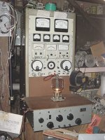
Absolutely yes. Years ago when I built my large tester for transmitting tubes, much like the kind in your icon, I experienced something I called "screen grid pull up". This is a condition where the screen would want to follow the HV potential on the plate. While testing, both control grid and plate would be set to predetermined levels. Then the screen would be brought up to to begin conduction. As the required level was approached, the tube would suddenly take off and draw tremendous current causing me to shut down the power as fast as I could or loose the tube to self destruction.Maybe a tetrode or pentode could reach cathode saturation at high enough g2 voltage without going positive on G1.
Well, to make the story short, it wasn't gassy tubes and they weren't oscillating. It was because the unregulated screen supply's output impedance was too high. The fix was to add a high wattage 10K ohm resistor across the supply's output. This prevented the screen from pulling up. And just so you know, there are non-inductive carbon stopper resistors under the plug-in socket assembly.
Now even though these were large industrial tetrodes, the premise can be scaled down a little and should verify your thought.
Attachments
Last edited:
"I experienced something I called "screen grid pull up"."
I'm not sure that's cathode saturation you saw.
That sounds like screen emission, where the screen gets hot enough to emit electrons, like a cathode, and current is drawn from screen to plate.
A pull-up or follower can't sink any current, can only regulate in the positive direction, not negative. So even if the calculted impedance of a follower is very low, if it can't sink current as well as source, the g2 may run away. I think it's a possibility for g1 to run away also, if operated in A2 and there is not enough pull-down resistance. Gassiness can cause it also.
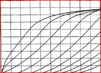
Here are curves from a tube model that show the cathode saturation region, where the curves flatten out at the top.
I imagine there is often some other limit, like grid emission, reached before cathode saturation in most practical cases.
There is another limit that may apply to the original question; on a particular load line, the plate voltage can only go so low before the plate current stops increasing. I believe this is known as "diode mode saturation" or something like that. On pentode curves the minimum plate voltage is called the "diode line". The cathode doesn't saturate in this case, but rather the grid(s) will start drawing current from the cathode instead.
Cheers,
Michael
I'm not sure that's cathode saturation you saw.
That sounds like screen emission, where the screen gets hot enough to emit electrons, like a cathode, and current is drawn from screen to plate.
A pull-up or follower can't sink any current, can only regulate in the positive direction, not negative. So even if the calculted impedance of a follower is very low, if it can't sink current as well as source, the g2 may run away. I think it's a possibility for g1 to run away also, if operated in A2 and there is not enough pull-down resistance. Gassiness can cause it also.
Here are curves from a tube model that show the cathode saturation region, where the curves flatten out at the top.
I imagine there is often some other limit, like grid emission, reached before cathode saturation in most practical cases.
There is another limit that may apply to the original question; on a particular load line, the plate voltage can only go so low before the plate current stops increasing. I believe this is known as "diode mode saturation" or something like that. On pentode curves the minimum plate voltage is called the "diode line". The cathode doesn't saturate in this case, but rather the grid(s) will start drawing current from the cathode instead.
Cheers,
Michael
Attachments
That sounds like screen emission, where the screen gets hot enough to emit electrons, like a cathode, and current is drawn from screen to plate.
RDH4 has a nice description on page 21.
RDH4 has a nice description on page 21.
Nice. Pages 17-23 pretty much cover the subject. One feels humbled...
Not in this case. The screen went very positive because it was approaching plate potential. But you are correct in that good (new) tetrodes will experience negative screen current of a few milliampes. As they age it can become positive and it's one of the things to watch for when testing. You can't see it in the picture but the screen current meter (second from left in the row of 4) is center scaled to reveal either.Was this an example of the negative screen current which some big tetrodes can do?
You can run a single tube with grid current, Class A2, or a pair of tubes in push-pull with grid current, Class AB2, provided that the grid is sufficiently rugged to withstand the current and the grid is driven by a suitable low impedance source.
Class C has nothing at all to do with grid current; it concerns what happens at the opposite (negative) end of the cycle, namely, cut-off.
You're perfectly correct, I relied on an imperfect memory, and worsened the situation with a throw-away remark.
Still, it got things moving, everybody here is scared to commit on a subject like this, you just open yourself to a blast of nit-picking...
w
Nope, wasn't screen emission in the normal sense. Happened too fast with way too much total current. May not have been absolute total saturation because I didn't let it go. With 2000-2500 volts on the plate, the space charge wanted to elevate the screen as if it were floating because of it's high impedance source. This was to illustrate that a high enough screen potential can and will overcome the negative G1 control. In fact the screen grid has just as much (perhaps more) control of a tube's conductance as does the control grid."I experienced something I called "screen grid pull up"."
I'm not sure that's cathode saturation you saw.
That sounds like screen emission, where the screen gets hot enough to emit electrons, like a cathode, and current is drawn from screen to plate.
I wonder if screen emission is due to secondary emission rather than thermionic emission. It's rarely made of emissive materials, after all, doesn't get extremely hot in normal operation (are there any transmitter tubes designed to operate in toastergrid mode?), and has gobs and gobs of electrons streaming past it (some which impact). Depending on voltages and materials, secondary emission could easily exceed screen current (i.e., a secondary emission gain > 1). Certainly, in tetrodes, it's easy to observe secondary emission, but this is usually from the plate (plate current decreases as relative screen voltage increases, i.e., the plate is conducting to the screen because of secondary electrons, causing apparent negative resistance).
Regarding cathode saturation: the saturation spoken of here is voltage saturation, analogous to a BJT's saturation region, or a FET's ohmic region. It is NOT cathode saturation, because cathode current is well within ratings in this region, and it is not current saturation, which occurs at higher plate voltages, where the plate curves flatten out (the linear range, analogous to a FET's current saturation region).
Tim
- Status
- Not open for further replies.
- Home
- Amplifiers
- Tubes / Valves
- What causes saturation in tubes?