Your latest schematic is ill-defined with respect to DC bias. While you might make it work by selecting some parts even slight temperature drift will make the output hit the rails. Have you tried heating the input transistors a bit (e.g. with a heat gun)?
Are you referring to the fact that the cascode transistor bias is referred to ground, whereas in your schematic it is referred to the source of the jfet. Then in my schematic as the jfets heat up, their DC operating point shifts, but the bias of the cascode transistor doesn't, since its base is referred to ground?
Haven't tried to heat them up because didn't think about it. I did check and the jfets heat up quite a bit during operation, as well as the cascode transistor; the current through them is about 75mA. Left it on quite long and it didn't run into problems.
However, I will try to bias the cascode transistor as you do in your preamp, but will R5 (13k in your schematic) not be a large source of noise? Should it not be bypassed to ground?
The cascode causes the amplifier to have negative input capacitance over some frequency range. If the source has sufficiently high inductance and sufficiently low resistance the amp wil turn into an oscillator. You can fix this preferably by compensating the input Z by adding a suitable shunt element. In case of low negative capacitance a simple small capacitor (note C2 on my schematic) is usually enough. With many parallel high-C parts in the input you probably need a Zobel network. Of course there are many more instability sources, but this one will surely need your attention.
Samuel
Aha! For the Zobel network on the input, I just pull the values out of the hat or is there a proper way of calculating them? By the way, can you please point me to any where I can find out more about this negative input capacitance due to the cascode?
Are you referring to the fact that the cascode transistor bias is referred to ground?
No, I'm referring to the fact that you've removed both the large AC coupling capacitor (as in my schematic) and the servo (as in the design by syn08). This makes the DC gain 60 dB (compared to 0 dB). This works with (well-designed) differential input pairs where the Vbe/Vgs temperature dependence tends to cancel but not very well with single ended input stages. It just takes a 10 mV shift at the input for a 10 V output shift. You get 10 mV shift with BJTs simply from a 5 K temperature change. For JFETs it can be worse or better depending on the bias point.
For the Zobel network on the input, I just pull the values out of the hat or is there a proper way of calculating them?
You could simulate the input Z of the amplifier for a starting point. I guess something like 100 pF/1k Ohm might work.
By the way, can you please point me to any where I can find out more about this negative input capacitance due to the cascode?
"Wideband amplifiers" by Peter Starič and Erik Margan has a section on similar effects in source followers. They also derive the math to calculate the Zobel network. Other than that I don't remember a reference.
Samuel
Last edited:
No, I'm referring to the fact that you've removed both the large AC coupling capacitor (as in my schematic).
C3 or C5 in your schematic?
C3 or C5 in your schematic?
Which one is part of the feedback network of the first stage and can hence reduce DC gain to unity?
Samuel
Here's a comparison between the Denis Colin amp and the SSM2019. Remember that the SSM2019 has, essentially, 2 amplifiers and is operating at 1,000X:
An externally hosted image should be here but it was not working when we last tested it.
I wish I could read these confidently.
Do the two plots show Colin's as ~27dB less output noise at the HF end and ~35dB less output noise at the LF end?
Then we correct by subtracting the 20dB due to the +60dB & +40dB gains, leaving Colin's 7dB to 15dB quieter as effective input noise.
Do the two plots show Colin's as ~27dB less output noise at the HF end and ~35dB less output noise at the LF end?
Then we correct by subtracting the 20dB due to the +60dB & +40dB gains, leaving Colin's 7dB to 15dB quieter as effective input noise.
I know Andrew, but the colors are pretty!
So at 10kHz, 7.63nVrms vs 13.91nVrms input referred noise?
So at 10kHz, 7.63nVrms vs 13.91nVrms input referred noise?
C5 I think.
Right. C3 simply bypasses R4 to reduce the noise contribution of this resistor and for somewhat better PSR.
I wish I could read these confidently.
I hate these spectrum analyzer plots as well... I always import the data into Matlab where we have decent plot functions.
Samuel
I hate these spectrum analyzer plots as well... I always import the data into Matlab where we have decent plot functions.
When it comes to noise, absolute noise voltage values are almost as useless as reading noise on a scope screen. It's the noise density that matters, simply because it's frequency independent (at least for white/pink noise). Such absolute noise voltage plots are good only for relative estimations (and that assuming that the same RBW was set for all measurements).
Usually, you don't need MatLab. All decent analyzers I have seen had the option for PSD (power spectral density) plots. So it's just a matter of chosing the right settings.
Here's a comparison between the Denis Colin amp and the SSM2019. Remember that the SSM2019 has, essentially, 2 amplifiers and is operating at 1,000X:
Is that the $43 pre-amp? I agree on having the instrument compute the V/rt-Hz. It's tedious to compute the equivalent noise BW for each instrument state.
The circuit I last posted had several problems, as Samuel has noted already. But the worst was for me that I couldn't get rid of that oscillation when the input would be shorted. Tried the Zobel network with several values, no change.
I decided to pull out the bjt in the cascode, and even then it oscillated. I think it had nothing to do with the cascode, and much more to do with the opamp.
At this point you're probably sick and tired of me, but I opened the thread and will go on until I get one low noise amp the way I want it.
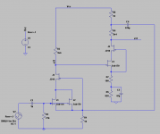
I had an idea of using a jfet for the cascode so I implemented the attached circuit. Some resistor values are different in the real circuit, this attached version is the one that simulated right. At least this, I'm sure, unsophisticated and stupid circuit didn't oscillate with a bomb at the input. So I could run a measurement.
You'll notice that only two jfets are paralleled, but I'll add more next time. This version measured a gain of about 400 at node a12. I want a gain of 1000, so maybe I'll add an opamp at the a12. For now, I was curious what noise this thing would be. I was hoping below 1nV/rtHz.
With a shorted output the HP 3585A measured 360nV/rtHz at 1kHz, and 340nV/rtHz at 10kHz. Divided by the gain of 400 I get 0.9nV/rtHz and 0.85nV/rtHz. I think these are sane values for this circuit. Or are they?
To parallel more jfet I'll need to use one J310 for each pair of K170. Do you guys think that'll be problematic?
Any input is, as usual, much appreciated.
I decided to pull out the bjt in the cascode, and even then it oscillated. I think it had nothing to do with the cascode, and much more to do with the opamp.
At this point you're probably sick and tired of me, but I opened the thread and will go on until I get one low noise amp the way I want it.
I had an idea of using a jfet for the cascode so I implemented the attached circuit. Some resistor values are different in the real circuit, this attached version is the one that simulated right. At least this, I'm sure, unsophisticated and stupid circuit didn't oscillate with a bomb at the input. So I could run a measurement.
You'll notice that only two jfets are paralleled, but I'll add more next time. This version measured a gain of about 400 at node a12. I want a gain of 1000, so maybe I'll add an opamp at the a12. For now, I was curious what noise this thing would be. I was hoping below 1nV/rtHz.
With a shorted output the HP 3585A measured 360nV/rtHz at 1kHz, and 340nV/rtHz at 10kHz. Divided by the gain of 400 I get 0.9nV/rtHz and 0.85nV/rtHz. I think these are sane values for this circuit. Or are they?
To parallel more jfet I'll need to use one J310 for each pair of K170. Do you guys think that'll be problematic?
Any input is, as usual, much appreciated.
Attachments
I'm still fooling with simulations of the previous circuit and am having a heck of a time getting the DC operating point where I think it should be. I think it's fundamentally flawed in that there's no way the output can put enough signal through the feedback to the input to correct for device variations. OTOH, I ain't done yet.🙂
Ah, good luck with that!
I quickly added another pair of K170 cascoded by a J310, in parallel with the other two. Unfortunately, the noise didn't seem to have gone down.
Ideally the noise would go down with the square root of the paralleled devices. For the 2sk170, the voltage noise is supposed to be about 0.95nV/rtHz. Paralleling eight of them should get the noise down to about 0.95/sqrt(8) = 0.336nV/rtHz. So I hooked up eight 2sk170 to a 150R load resistor and a 1R source resistor. This ended up with 29.2dB gain, or 28.84 times. Measure the noise of this thing and the HP reported about 18nV/rtHz. Dividing 18 by 28.84 should give the input referred noise, about 0.624nV/rtHz. This is quite a departure from the theoretical 0.336nV/rtHz.
For the record, I used two 12V lead acid batteries in series, which, together with the circuit, were enclosed in a cookie tin box. Just opening the lid made the noise a lot larger.
This is a bit disappointing.
Usually, you don't need Matlab. All decent analyzers I have seen had the option for PSD (power spectral density) plots. So it's just a matter of chosing the right settings.
I wasn't referring to the correct measurement of noise but merely to the fact that Matlab gives much better graphical support, i.e. much more readable plots.
Much more to do with the opamp.
The LT1028 is *not* unity gain stable. You need e.g. an LT1128 as you have a quite high value of feedback capacitance.
I'm still fooling with simulations of the previous circuit and am having a heck of a time getting the DC operating point where I think it should be. I think it's fundamentally flawed.
That's exactly what I pointed out a couple of posts back.
Samuel
Douglas Self give the improvement with doubling of input devices as -1.8dB. -3dB is only posible if the noise in the devices is totally uncorrelated. Nevertheless i was able to build Phonostages that came down to -146dB ref. 1V but only at higher frequencies where the RIAA shapes the noise.
Douglas Self give the improvement with doubling of input devices as -1.8dB. -3dB is only posible if the noise in the devices is totally uncorrelated.
He must have meant that the input device voltage noise must be the only significant contributer (i.e. doubling a bipolar stage will increase current noise). Devices in separate packages always have totally uncorrelated noise. Unless, of course, you place them both close to a Bybee. 🙂 (joke!)
I will reread what he found and then answer. As far as i understood it, despite the theoretical improvement of -3dB he could only measure -1.8dB.
- Home
- Amplifiers
- Solid State
- Simple 60dB discrete low noise amplifier (lna)