hello,
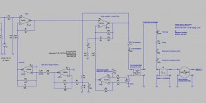
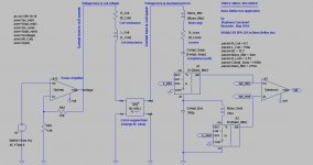
I've just completed a LTspiceIV toolbox for simulating some elaborate active loudspeakers. It is amazing to see the bandwith extension one can get using some kind of managed current drive.
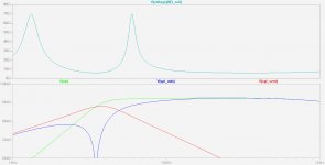
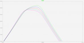
The current drive annihilates the 1st order lowpass at high frequency caused by the coil inductance. This is the reason why the bandwith now extends beyond 10 kHz. I definitely know this is a pure theoretical curve. In a real application, a high frequency roll-off may be desirable for compensating some real cone resonances above 2 kHz.
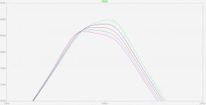
The deep bass voltage feedback annihilates the closed box resonances. You can see the effect of the deep bass voltage feedback when varying the feedback capacitor. There is an optimal value around 220nF where the bass is at -3dB at 30 Hz, an no closed box resonance anymore.
And we have not yet used motional feedback (coil back EMF extraction or piezo acceleration sensor). Actually, there is a piezo sensor model and schematic in the toolkit (Thiele-Small Reloaded with LTspiceIV.zip). Use this !
You may also use the toolkit for modelling the effect of a passive filter inserted between a power amplifier and a closed box loudspeaker.
Later on I'll release a 4th order bass-reflex toolkit and possibly also a 4th order bandpass (double chamber) toolkit.
See attached files.
Any suggestion or question welcome.
Steph
I've just completed a LTspiceIV toolbox for simulating some elaborate active loudspeakers. It is amazing to see the bandwith extension one can get using some kind of managed current drive.
The current drive annihilates the 1st order lowpass at high frequency caused by the coil inductance. This is the reason why the bandwith now extends beyond 10 kHz. I definitely know this is a pure theoretical curve. In a real application, a high frequency roll-off may be desirable for compensating some real cone resonances above 2 kHz.
The deep bass voltage feedback annihilates the closed box resonances. You can see the effect of the deep bass voltage feedback when varying the feedback capacitor. There is an optimal value around 220nF where the bass is at -3dB at 30 Hz, an no closed box resonance anymore.
And we have not yet used motional feedback (coil back EMF extraction or piezo acceleration sensor). Actually, there is a piezo sensor model and schematic in the toolkit (Thiele-Small Reloaded with LTspiceIV.zip). Use this !
You may also use the toolkit for modelling the effect of a passive filter inserted between a power amplifier and a closed box loudspeaker.
Later on I'll release a 4th order bass-reflex toolkit and possibly also a 4th order bandpass (double chamber) toolkit.
See attached files.
Any suggestion or question welcome.
Steph
Attachments

Last edited:
Hi Steph
Yes sadly this does not happen in real life.
I've seen interestingly, that modeling Le and Re using a first approximation ie 1st order roll-off and the actual cones response off axis have some good correlation. Also we know that cones off-axis frequency roll-off is related to the of departure of the cones simple pistonic frequency range.
I think your work is good so far as I have toyed a little with it using LTspice. but I think most folks in this forum can't relate too much to these particular sims ie current or motional feedback, Concentrating on the driver only model first might be a good idea to this audience? Can you show that your driver model is true, before feedback is applied. Probably the best thing here is to perfect the driver model first using a real driver in a closed box. Seems you should be able to get good correlation to the accepted software modeling simulation programs and even possibly verifying them with open loop measurements using current and voltage drive. What do you think?
Excellent suggestion ! Please post the names of three different accepted software modeling simulation programs, please post the names of three different drivers to be simulated, and I'll compare the simulation results.Can you show that your driver model is true, before feedback is applied ? Probably the best thing here is to perfect the driver model first using a real driver in a closed box. Seems you should be able to get good correlation to the accepted software modeling simulation programs and even possibly verifying them with open loop measurements using current and voltage drive. What do you think ?
Steph
T/S simulation software (driver data base may or maynot be accurate)
Unibox
WinISD
BassBox Pro available here
I have used Unibox and WinISD some/ not tried BassBox yet.
We could use your Monocor SPH-225C and modest 8" Silver Flute W20RC38-08 Silver Flute W20RC38-08, 8" Wool Cone from Madisound
Unibox
WinISD
BassBox Pro available here
I have used Unibox and WinISD some/ not tried BassBox yet.
We could use your Monocor SPH-225C and modest 8" Silver Flute W20RC38-08 Silver Flute W20RC38-08, 8" Wool Cone from Madisound
Last edited:
hello,
The current drive annihilates the 1st order lowpass at high frequency caused by the coil inductance. This is the reason why the bandwith now extends beyond 10 kHz. I definitely know this is a pure theoretical curve. In a real application, a high frequency roll-off may be desirable for compensating some real cone resonances above 2 kHz.
Steph
I have noticed the same when looking at a large number of full range driver response and impedance curves. The response generally tracks the inverse of the impedance curve. Current drive, at least at the top end, will generally give a flatter response.
Makes sense from and F = BLi = ma point of view. Constant current give constant force or acceleration. Very generally, a curve off axis, say 45 degrees off, becomes flattest on a lot of drivers, in current drive.
I think Nelson Pass published something on this.
David
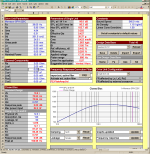


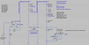
Everything is natively handled by the equations generated by the circuit topology. Of course, you need to provide the parameters in the MKS (meter-kilo-second) standard. Velocity is native in meter/sec, acceleration is native in m/s2, and excursion is native in meter ! You can read those three in the dedicated coupler's outputs (left side), ground referred. Isn't this beautifull ?How do we relate the model to physical parameters?
The only "constant" is the SPL sensitivity embedded in the SPL section of the "coupler" subcircuit. This is the only place where you'll see a constant, associated to the calculation of the membrane surface, used to set the SPL sensitivity of the model, with this constant being set for getting a model that equates the sensitivity of some other simulation softwares.
Later on I'll replace this bare dirty SPL sensitivity constant by a combination of physical constants related to the 20µPascal standard. You won't see the difference in the result, or maybe one tenth of decibel or one decibel.
The fact that the bass-reflex topology behaved very well, makes me more confident. Now I know that this model is reliable.
See for yourself. Graph the membrane excursion. Graph the vent air speed. (You need to add the corresponding .save directive, or erase all the .save directives).
Now I'm trying to find the topology that corresponds to the 4th order bandpass (two chambers). That's not easy, conceptually. Is there litterature about this ?
Steph
Last edited:
Later on I'll replace this bare dirty SPL sensitivity constant by a combination of physical constants related to the 20µPascal standard. You won't see the difference in the result, or maybe one tenth of decibel or one decibel.
Ok that was my concern from before. Mostly that the elect input doesnt affect the sensitivity correctly.
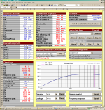
As for as parameters> I meant box volume and vent tuning Vb Fb ie relating to capacitance and inductance.
Yes very nice, indeed.The fact that the bass-reflex topology behaved very well, makes me more confident. Now I know that this model is reliable.
See for yourself. Graph the membrane excursion. Graph the vent air speed. (You need to add the corresponding .save directive, or erase all the .save directives).
AESNow I'm trying to find the topology that corresponds to the 4th order bandpass (two chambers). That's not easy, conceptually. Is there litterature about this ?
4th order bandpass the equations? I'm sure you can find them online someplace. You are the smart guy here.
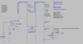
Here is the bandpass template.
But wait a moment : the box volumes are maybe impractical, too small ? And the vent is maybe quite large, compared to the box volumes ?
For verifying this I need to display the correspondent volumes in litres : box1, box2, and vent. If you are dealing with a 10 inch speaker, and if you need box volumes only a few liters, plus a 10 litre vent, then you know the design can't be materialized. How to implement those alarm signals under LTspiceIV ?
P.S.
While checking vent air speed, I've just realized that the vent air speed, excursion and acceleration still need to be multiplied by the factor equal to the ratio of membrane surface to vent surface. I thus need two different sorts of couplers : a membrane coupler where this factor is not present, and a vent coupler that has the knowledge of the membrane surface and vent surface. I'll update the toolkit accordingly. The SPL output is not affected by this omission because the vent air speed speed gets multiplied by the ratio, and later on, the SPL output gets divided by the same ratio, because SPL is proportional to the vent surface. The smaller the vent surface, the bigger the air speed, but the SPL remains the same. Of course if you chose a small surface vent, it needs to be long (deep) for keeping the air mass constant.
Cheers,
Steph
Attachments
-
 Monacor SPH-255 bandpass.jpg152.1 KB · Views: 256
 -
 Monacor SPH-255 bandpass (Bode plot).jpg103.3 KB · Views: 229
 -
Monacor SPH-255 bandpass.zip186.1 KB · Views: 60
-
 Monacor SPH-225C bandpass.jpg149.8 KB · Views: 252
 -
 Monacor SPH-225C bandpass (Bode plot).jpg100.6 KB · Views: 231
 -
Monacor SPH-225C bandpass.zip182.4 KB · Views: 71
Don't forget the physical vent can be located in either chamber.
You need an alarm for vent speed as well.
Note If the electrical terminals don't interact well with the model I'm doubtful of why anyone would use this. Maybe only if buffered by an amp, but that limits passive solutions or the reason to use SPICE in first place. There many better simulation programs that are more accurate. IMO
I've now updated the toolbox. The new .zip contains some nice exercise around the Monacor SP-100-8 driver. Please have a look to the negative and positive resistance drive schematics. Do you see any dogs in there ? What do you mean by "if the electrical terminals don't interact well with the model" ? Take some time opening and reading the internals of the two coupler subcircuits (MembraneCoupler and MembranToVentCoupler). Any comment much appreciated. Thanks.If the electrical terminals don't interact well with the model I'm doubtful of why anyone would use this. Maybe only if buffered by an amp, but that limits passive solutions or the reason to use SPICE in first place. There many better simulation programs that are more accurate.
p.s. 1
Is there litterature about the equivalent schematic of the 8th order bandpass (aka Bose) ?
p.s. 2
Any idea how to practically generate the "too small box" and "too big air speed" in LTspiceIV ?
Regards,
Steph
Attachments
- Status
- Not open for further replies.
- Home
- Loudspeakers
- Multi-Way
- Monacor SPH-225C - advanced current drive