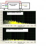
Greetings. I have a problem with noise induced in a device by the usb interface power. The device consists of a sensor and an analog to digital converter. The converter is powered by 5v from the usb and uses the usb for data transfer. When powering the sensor from the usb, there is a lot of noise. When powering the sensor from a battery the noise is much lower.
What kind of filter can I use for the sensor considering the sensor needs 5VDC and 5mA power input ?
What kind of filter can I use for the sensor considering the sensor needs 5VDC and 5mA power input ?
Attachments
Last edited:
Have you tried putting a 10uF-or-so electrolytic capacitor (not a low ESR type) in parallel with a 0.1uF (not NPO or C0G type), from 5V to gnd, right at the 5V input to the sensor and right at the 5V input to the converter? (i.e. One pair for each 5V input.) Use shortest possible leads and connect as closely as possible to 5V input pins. In particular, connect 0.1uF caps as closely as possible to the 5V input pins. You could vary the cap values and see what happens, too.
You might want to take the sensor's caps' grounds to the main USB ground, i.e. not to the one that comes through the converter. I would probably try it both ways, just to see what happens.
Depending on how much current is drawn, you might also be able to put a 10-to-100-or-so Ohms resistor (metal film type) in the 5V line, just before the caps to ground at the converter, to form a better low-pass filter. Try something like 33 Ohms, maybe.
If the current draw is small-enough, you could put another resistor in the 5V line just before the caps at the 5V input of the sensor. I would probably take the 5V for the sensor from _before_ the resistor in line with the converter's 5V input. But you should try it both ways.
You should also see what happens if you connect the sensor's ground directly to the USB ground, instead of having the sensor share the ground run with the converter.
I would probably try using the largest resistances I could use, vis-a-vis the current drawn vs the voltage drop, to get the most filtering.
You might also want to try using a cap pair to gnd right at the USB 5V/gnd OUTPUT, if you use a resistor before the converter's 5V input, so that you also low-pass filter the noise going back INTO the USB 5V output.
Cheers,
Tom Gootee
Last edited:
It looks to be low frequency, but try a ferrite on the cable. If you've got a high-mu toroid, try a dozen or so turns. There might be more than one cause so don't remove any fixes until you can see it's gone. Then you can try removing them to see if it comes back.
I had a really nice handheld Tektronix scope. It never really worked as good noise-wise on its mains supply as it did on batteries, so don't expect miracles.
w
I had a really nice handheld Tektronix scope. It never really worked as good noise-wise on its mains supply as it did on batteries, so don't expect miracles.
w
For that low current, try a simple RC filter. Something like 10 ohms and 100uF or so.
Yahhh mon! Dat prolly be goood (enough).
there must be some voltage headroom to spare, as regulator will always drop some voltage. You can not get "clean" 5V output from "dirty" 5V input.
Even with simple RC filter there will be voltage drop on resistor. Ohm law is working against you 🙂
And feritte beads will "kick in" only at MHz range, at audio frequencies they do nothing.
Even with simple RC filter there will be voltage drop on resistor. Ohm law is working against you 🙂
And feritte beads will "kick in" only at MHz range, at audio frequencies they do nothing.
Last edited:
The usb spec requires not using more than 10uF as input cap. It's better to look for another solution.For that low current, try a simple RC filter. Something like 10 ohms and 100uF or so.
Back with an update. I've tried so far
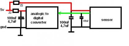
A/D converter powered through a 22ohm resistor followed by a 4.7uF and a 100uF capacitor and the sensor powered separately through the same value resistor and capacitors. No change.
I've tried to power the sensor through a fast diode and still no change.
Switched PC's and the noise is the same.
I have a clip uploading to show the fluctuating noise in the 20-2000Hz spectrum. It looks like it's pulsating.
Tried battery power again and the noise magically drops and the pulsation stops.
What can I try next ?
Attachments
As far as I can tell that usb isolator uses power from an external source. I've tried external power (see the battery vs usb power picture) but I want everything to be usb powered
first you need to find noise source:
- is noise coming from "ground"?
- is noise coming from power line (+5V)?
- is noise coming from "ground"?
- is noise coming from power line (+5V)?
should I try a resistor in series with the ground ?
tried in series with the positive and no change
tried in series with the positive and no change
I just tried resistor on ground, resistor on positive, resistors on both (10 to 33 ohms). Nothing. Decoupling capacitors 10nF, 100nF, 220nF, 470nF and even 1uF + 4.7uF electrolithic. Absolutely nothing changes.
Other things I can try ?
Other things I can try ?
I had the same problem with a PC based output to a Red Wine DAC with USB input.
The solution that finally worked? I hate to admit it...a Mac. Also worked to run a laptop on batteries. No noise at all. I think the PC, at least HP in my case uses a crap power supply. The isolator might work, or go Apple....
The solution that finally worked? I hate to admit it...a Mac. Also worked to run a laptop on batteries. No noise at all. I think the PC, at least HP in my case uses a crap power supply. The isolator might work, or go Apple....
I think his software won't work on a Mac. 😛 Anyway you are right in one aspect - the $10 PSU is probably responsible for all the noise. Personally i'd just get a real power supply, i've had two very rare server boards blow up due to a dodgy PSU and it wasn't funny. But if you want to filter it at your device you're going to need Pi filters (cap, coil, cap). Aka what was supposed to be included in your power supply.
That's directly at the port. If you have a resistor to limit the peak current, you can use as much as you like. 10 ohms will limit peak current to 500mA.The usb spec requires not using more than 10uF as input cap. It's better to look for another solution.
Like I said, this can be an extremely intractable problem. I just used the battery when noise was critical.
There is a great deal of hash on the mains in many locations aside from that created by whatever PSU you have. It's created by dimmers, switchmode supplies, all kinds of things. Turn them all off in the locality if you can.
Don't be cavalier about the higher frequencies. You no more want RF in an A/D than you want it in an amplifier. The mechanism whereby this is occurring is by no means clear. High frequencies can be detected or translate to (beat) or otherwise excite lower frequencies. Switching artifacts have low periodicity but fast risetimes. A fast risetime can breeze past low frequency filtering, but appear tick, tick, tick, at 120Hz. Apply the ferrites and bypass all the filter caps.
What are the lines on the video which seem to be independent of the low frequency hump that comes and goes?
It would help if you were a little less coy about the details of the hardware and software and managed to get the video in focus. Is this a product you are developing? It's a realtime FFT is it?
w
So did you ever fix this?
Have you tried an inductor followed by a large capacitor to ground? (You could also put a small resistance in series to damp the resonant peak at the cutoff frequency, if that's a problem. You could then also put a capacitor before the inductor, to make an even better filter.) Something like 10-100 uH and 1000-2200 uF should kill about anything. I would stick 10-47 Ohms ahead of it, though, and would probably then also put an additional cap to ground between the R and the L.
Also, depending on what you're measuring with the sensor, you might be able to filter the sensor output.
But you really do need to figure out what kind of noise it is. For example, maybe the "ground" is bouncing around. Common mode vs differential mode? RF getting rectified in semiconductor junctions? Etc.
Do you have an oscilloscope?
- Status
- Not open for further replies.
- Home
- Amplifiers
- Power Supplies
- usb power noise filtering