A good article for sure but I wouldn't call this a missing link; rather a link that goes unchecked by most of the population.
Good article, but there still something missing. The real goal is how to add the sound waves into the environment without causing any distortion to the existing wave and the sound waves added is not distorted too.
There is some problem with maintain the damping factor and its effect to the environment waves. Lets says that we reduce amplifier DF with inserting resistor in series at its output. It will be different if we reducing the damping factor using current reference as in circuit above.
I have two more factor to determine the differences that will happened in DF maintenance, says the first is Destruction Force of amplifier, and the second is Cooperative Alignment of amplifier, since I can not prove it, its just an issue.
Using resistor in series with ideal voltage source will make it no destruction force and neutral or no cooperative at all.
Last edited:
Member
Joined 2009
Paid Member
Good article, but there still something missing. The real goal is how to add the sound waves into the environment without causing any distortion to the existing wave and the sound waves added is not distorted too.
There is some problem with maintain the damping factor and its effect to the environment waves. Lets says that we reduce amplifier DF with inserting resistor in series at its output. It will be different if we reducing the damping factor using current reference as in circuit above.
I have two more factor to determine the differences that will happened in DF maintenance, says the first is Destruction Force of amplifier, and the second is Cooperative Alignment of amplifier, since I can not prove it, its just an issue.
Using resistor in series with ideal voltage source will make it no destruction force and neutral or no cooperative at all.
I'm not sure I understand your concerns. The first item says to me that you want to avoid the sound generated by a speaker from interacting with sound already present in the environment or perhaps the speaker being affected by environmental sound waves ? that's an interesting question and I don't know the answer ! I always assume that we try to find a quiet place to listen to our hi-fi so that we aren't disturbed by other sound sources.
With regards Damping Factor - I'm not convinced myself that the concept of DF is a safe starting point. It's already a simplification, a ratio of two impedances which themselves vary with frequency in different ways. I think the article I linked makes it clear that you have a more complex situation and you need to look carefully at the details.
As for a resistor verses 'current feedback', I'm not sure what you mean here. I have to admit that I find the terms 'voltage feedback' and 'current feedback' as bad as DF - these terms aren't very helpful in describing what is going on. I agree that it's unlikely the feedback system described earlier will produce the same results as a simple resistor at the output but they may both give you an extra degree of control over the amplifier & speaker which allows you to have some fun !
Single speaker will have its resonance, nonlinearity(impedance, freq response,etc), its low efficiency, and more, that some was wrote on that article. Also it has self acoustic feedback, box reflex, and wave reflected by walls and more that not wrote there. Two speaker will more complex than single, interact between two speaker, wave direction changed, sensitivity too, and more also not wrote there.
If we try to use full damped room and single speaker with full damped box, driving loudspeaker to moving as the input voltage is just fine (even with voltage source).
May be someone that has playing in DF adjustment will found something about what I mean. Destructive Force has correlation with amplifier speed, and Cooperative Alignment more depend on feedback type and its ratio.
Like I have told before, it is just an issue, and very difficult to understand.
How about try it. Reduce DF with Resistor and Current Feedback to the same damping factor. There may any different sound.
Last edited:
Onto: Please tell me how using a resistor is going to be that much different from a well-linearized amplifier with an output impedance of the same value as that resistor?
I need more clues and experience to answer that, my current experience is not enough. I can only describe what I have found and may be only guessing.
With this is happening, my two added factor may helpful in DF adjustment project, to achieving as good as possible configuration.
There are many type of alignment that may drive or even force the loudspeaker to do as amplifier driven by input, which resistor can only damping it.
I hope that someone experienced well, join this discussion and giving us any clues and help, also sharing their experience.
Just keep forward, it is not a bad starting, may be you'll find something that I don't. DF is one of the key of sound quality as I know. But it is very hard to describe what happening exactly.
May be carver has fail here, but there are others that used this technique like yamaha. I used to call it V+I technique, because before it, I am trying to create VxI amplifier, or a power source, but it failed. 😀
Last edited:
It seems you're more just guessing at this than understanding what DF actually is in essence?
The effect here is extremely simple and I can prove my results with according FFT and oscillograph measurements. The damping factor of amplifiers, in simple and known terms, is the ratio of the amplifier's output impedance to the speaker's characteristic impedance.
This means that DF is not a constant for any system, but varies with frequency given a speaker's natural impedance curve across its useful range. What it also means is that the shape of the curve (in terms of impedance) remains the same; therefore, the overall effect of damping factor being changed is a consistent one across the frequency range in terms of impedance relative to the driver(s) in use.
If you take your resistor analogy against an amplifier with an arbitrary output impedance and measure the two setups, you can see that the result is exactly the same.
A terribly crude example I give some friends who don't understand this in engineering terms is to show impulse response of a given driver on an oscilloscope. Impulses are applied while the amplifier's output impedance is varied and the effect of this can be seen very clearly on the oscilloscope around the driver's resonance. One could also produce stimulus acoustically using another driver near the test driver and watch the same effect occurring.
If you would, Onto: please explain these two "added factors" you consider helpful in developing a variable output impedance amplifier. I believe you are attempting to complicate simple engineering theory with guesswork.
Last edited:
Ofcourse I cannot prove it without measuring the wave with B&K microphones in a dumped room, etc.
What about just make your project finished and we may sharing in something.
It will not end to talking something that we just didn't found yet.🙄
If you need pre discussion, you need people that already found it. Says experienced man, if there is any, I will lovely join the discussion. I see a simple schematic here with both DF management and two type of positive feedback. What positive FB used for, what exact proof says?, what is missing?
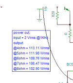
This is sim result example from current fb, consider it with resistor.
What about just make your project finished and we may sharing in something.
It will not end to talking something that we just didn't found yet.🙄
If you need pre discussion, you need people that already found it. Says experienced man, if there is any, I will lovely join the discussion. I see a simple schematic here with both DF management and two type of positive feedback. What positive FB used for, what exact proof says?, what is missing?
This is sim result example from current fb, consider it with resistor.
Attachments
Last edited:
Your simulation, by my calculation, is for an amplifier of approximately 4.5ohms output impedance; so effectively you have not simulated an amplifier with good current feedback.
If you calculate the current at each output level, you find that the currents are as follows:
113.11W @ 4ohms = 5.32A
111.98W @ 5ohms = 4.73A
109.76W @ 6ohms = 4.28A
106.47W @ 7ohms = 3.90A
102.90W @ 8ohms = 3.59A
You can calculate the output resistance by taking differences between the loads and my result is approximately 4.5ohms, but this changes slightly between measurements so also your simulation shows some error in the output impedance, all else being equal.
A true current feedback (high output impedance) amplifier will show virtually no variation in output current with different load impedances.
The intent of having a variable output impedance amplifier is to allow the user to arbitrarily set the output impedance, which in effect is the same as putting different resistances in series with the output of a given amplifier with zero ohms output impedance (minus the effect of power and voltage loss).
If you take the Trans-amp and set its output impedance to 4.5ohms, or take some other typical solid state amplifier and stick a 4.5ohm resistor in series with its output, the effect seen at the speaker is the same. In the latter case you just end up wasting more power with the resistor and give up useful voltage before clipping.
Lets start the second step.
Add a small sinus source (1volt is enough) between load and amplifier.
Add a small sinus source (1volt is enough) between load and amplifier.
Matter of fact; I can take a power supply transformer and connect its secondary right up to the output of my transamp and get the same effect as putting a resistor on said transformer.
If I set the output Z to 10ohms and connect a sine wave of 1V (or any wave for that matter) within the operating frequency range of the amplifier, I will find that the current between amplifier and transformer is 100mA. Would the same not occur if I connected a plain 10ohm resistor to said sine wave source?
If I set the output Z to 10ohms and connect a sine wave of 1V (or any wave for that matter) within the operating frequency range of the amplifier, I will find that the current between amplifier and transformer is 100mA. Would the same not occur if I connected a plain 10ohm resistor to said sine wave source?
Wrong, the next step is about timing and lagging
output:
@4ohm = 113.11 Wrms with1vrms:109.46Wrms 21.27v-20.92v=0.35 loss 0.65
@5ohm = 111.98 Wrms with1vrms:108.77Wrms
@6ohm = 109.76 Wrms with1vrms:106.20Wrms
@7ohm = 106.47 Wrms with1vrms:103.24Wrms
@8ohm = 102.90 Wrms with1vrms: 99.76Wrms
output:
@4ohm = 113.11 Wrms with1vrms:109.46Wrms 21.27v-20.92v=0.35 loss 0.65
@5ohm = 111.98 Wrms with1vrms:108.77Wrms
@6ohm = 109.76 Wrms with1vrms:106.20Wrms
@7ohm = 106.47 Wrms with1vrms:103.24Wrms
@8ohm = 102.90 Wrms with1vrms: 99.76Wrms
Why you need to make amplifier that will have same as if there resistor series with it?
Hear it first, Voltage Amp with resistor series at output is not nice sound.
Hear it first, Voltage Amp with resistor series at output is not nice sound.
I'm having great trouble seeing what you're trying to say. Just for some empirical proofs I put my transamp on the bench tonight and did some unusual tests.
Test A: Use the amplifier as a variable resistor: By placing a 12V transformer in series with the amplifier output and a 30 ohm resistor I could set the voltage across the 30 ohm resistor to near zero or near full 12V by adjusting the amplifier's impedance knob. If for example I set it to 10ohms and measure the voltage and then replace the amplifier with a 10ohm resistor; I get the same voltage across the resistor, regardless of supply waveform.
Test B: Use the amplifier as a variable resistor in a more unusual case: I've connected the output of the transamp in series with the output of another audio amp and a speaker. This allows the use of the transamp as a variable power resistor in effect. I can play audio on the other amplifier and use transamp to control the volume to the speaker. Of course this proves again that the amplifier is acting as a variable electronic resistor in essence, which is what I intended in the first place.
Why you need to make amplifier that will have same as if there resistor series with it?
Hear it first, Voltage Amp with resistor series at output is not nice sound.
I disagree: Try different output impedances with different speakers. Some sound far better with less damping for reasons discussed at the start of this thread.
I'm having great trouble seeing what you're trying to say. Just for some empirical proofs I put my transamp on the bench tonight and did some unusual tests.
Test A: Use the amplifier as a variable resistor: By placing a 12V transformer in series with the amplifier output and a 30 ohm resistor I could set the voltage across the 30 ohm resistor to near zero or near full 12V by adjusting the amplifier's impedance knob. If for example I set it to 10ohms and measure the voltage and then replace the amplifier with a 10ohm resistor; I get the same voltage across the resistor, regardless of supply waveform.
Test B: Use the amplifier as a variable resistor in a more unusual case: I've connected the output of the transamp in series with the output of another audio amp and a speaker. This allows the use of the transamp as a variable power resistor in effect. I can play audio on the other amplifier and use transamp to control the volume to the speaker. Of course this proves again that the amplifier is acting as a variable electronic resistor in essence, which is what I intended in the first place.
Sorry for troubling you, I don't mean to do that.
Doing test is most useful, instead of talking discussing something that we don't know, and no teacher joining. I know DF is one of biggest unsolved problem in amplifier world. But experience is still helpful for audio amplifier designer.
Everything I have posted thus far is based on empirical tests and experience to the best of my knowledge. I am not basing this concept or amplifier on mere speculation, but on real-world application and results.
- Status
- Not open for further replies.
- Home
- Amplifiers
- Solid State
- That curious extra knob, or: "Trans-Amp"