thanks guys it appears that the Bypass capacitor is omitted in this illustration of the UL cascode.. Still haven't removed that from mine yet
Hey MerlinB,
Now you got me obsessed😀.
Used my old E88CC cascode RIAA as test-bench to verify. Tried a brand new JJ 802S and gain is higher at just below 40dB at Ua 180V, Ia 7mA.
But that implies a Gm of almost 1,7mA/V not 1mA/V with load 91k/208k/1Meg=59k as in ppl´s amp.
But let´s say I have no expectations at all of the tube🙂.
Ah yes, I forgot the 200k!But that implies a Gm of almost 1,7mA/V not 1mA/V with load 91k/208k/1Meg=59k as in ppl´s amp.
Ah yes, I forgot the 200k!
Suspected it was something like that, as you seem to know what you´re talking about😎.
This a simplified Schade where the pentode should be substituted for a cascode.
Last edited:
Once again thanks for your thoughts. I removed the cap across the lower voltage divider and the instability went away. Open loop gain also dropped by about 5-6 db this however did not affect the closed loop gain or the clipping point. Further research revealed that this cap might be causing some sort of bootstrap effect, of perhaps some mild form of Feedfoward.
Sonically the change was quite dramatic as far as differences between Electronics go. The sound stage dramatically improved the top octave is not as bright in fact it could now use a little more sparkle. Dynamically at first appeared substantially reduced and the previously aggressive nature of the amp became one of a polite refined nature somewhat similar to the old QUAD I as I remember it. It is quite clear that for my liking the amp now needs Re-voicing Perhaps, next Wk.
I previously tried Active current source loading using a string of 1N5309’s gave great measured performance a nice top end however did add a noticeable solid state Sound to the Amp that I did not prefer. I have been very tempted to drop in an EF184 in place of the 12AT7.
Like some of you I would have liked to use a higher value resistor than 200k for the Grid Leak on the output tube, however I notice many NEW manufacture tubes recommend 220K as a MAX G1 resistance. I may however up that to the standard 470K since I see a lot of designs using new manufacture tubes using this high a value of G1 resistance. Referring to the Design posted by revantage, Would (R2) the 68K resistor applying local feedback around the output tube also present the driver win an abnormally low Load. Moreover, would not such a low load resistence sort of take away a lot of the advantages of Active Plate Loading?
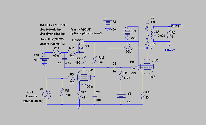
Hey ppl,
This is the cascode version. The cascode is working like a current-source in this configuration. Due to this, 15-20mA works best, with this one at 15mA.
The "gyrator" on top controls the Ua and also gives a really good PSRR. It doesn´t load the cascode either so the driver can deliver all current into the next stage.
It will give up something like 7-9W of triodelike power. Also Zout and distortion pattern is like from a triode amp.
Attachments
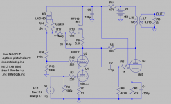
Why do you prefer gyrators? I would have thought an ordinary CCS would be preferable since it's impedance is more constant with frequency?The "gyrator" on top controls the Ua and also gives a really good PSRR.
Hey Merlinb,Why do you prefer gyrators?
In this case its not about prefering its a absolute must. As the pentode/cascode is a current source a CCS will work against it with Ua all over the place.
Otherwise I like it better even for triodes as it works more like a choke and I really like choke/transformer-loading. This is the nearest soundwise.
I removed the NE-2H NEON Lamp string on the output tubes and put the resistor back in so now the output stage is as it was. The sound changed from a nice tight almost solid-state bass to a slightly fat yet still controlled low end. Going to the voltage Divider on the output stage from NEON, Reduced the Amp’s open loop gain just like removing the capacitor from the Input cascode as previously discussed. Using the resistor voltage divider on the output tube obtains Ultra linear operation of the output stage however, does not include the output transformer within the local loop. The advantage I like about this method is the improved stability over using the Transformer tap and the ability to control the amount of UL operation as one could simply install a Pot and Dial in anything from TRIODE to pentode Operation, if desired. Unlike the cascode input stage, the Tetrode/pentode tubes draw screen grid current so the resistors used in the voltage divider need to be the less sonically desirable power type. Technically a low inductive resistor such as metal oxide would fit the bill however, these to my ear sound dreadful and sonic qualities of resistors are important in this application.
Due to all the local feedback loops, I now have only about 6 db of overall Feedback. This sonically is not an issue however the bass boost is now minimally effective somewhat like a slight bass tilt, so I must ether reduce the closed loop gain or raise the open loop gain to get more action on the bass boost. Again not that any more Boost is needed on quality program material.
Attached is the schematic as the Amp is now I used EL34’s this time since I did not have any 6L6’s in the shop so the Voltages are based upon the GT EL34M and the JJ ECC81. Also along smiler thoughts is US4647872
Attachments
Hey ppl,
This is the cascode version. The cascode is working like a current-source in this configuration. Due to this, 15-20mA works best, with this one at 15mA.
The "gyrator" on top controls the Ua and also gives a really good PSRR. It doesn´t load the cascode either so the driver can deliver all current into the next stage.
It will give up something like 7-9W of triodelike power. Also Zout and distortion pattern is like from a triode amp.
Could this design work as a PSE 807 ?
yes this amp sounds great I have made some changes to the 12AT7 Driver stage I changed the 90k plate resistor to 130k for more gain. I Imaging an 807 would work in this circuit. It is my understanding that an 807 is simply a 6l6GC with a Different Pin out? i have tried several output tubes.
The 6L6GC,KT66,KT88,6550,EL34,KT77. and they all plug and play Hear the 6l6 gets about 18 volts across 300 Ohm cathode resistor an EL34 about 16 Volts and 22-23 volts for the KT88 and 6550 respectively. if you sub the GZ34 for the 5Y3 or 5U4GB the 6V6GTA will work, The 5Y3/6V6GT is what i use for headphone use... Attached is the power supply section for those of you that wish to make a copy of this Amp for your own use. Again this is a working schematic shown with all the parts I added during this sojourn into the thermionic world
The 6L6GC,KT66,KT88,6550,EL34,KT77. and they all plug and play Hear the 6l6 gets about 18 volts across 300 Ohm cathode resistor an EL34 about 16 Volts and 22-23 volts for the KT88 and 6550 respectively. if you sub the GZ34 for the 5Y3 or 5U4GB the 6V6GTA will work, The 5Y3/6V6GT is what i use for headphone use... Attached is the power supply section for those of you that wish to make a copy of this Amp for your own use. Again this is a working schematic shown with all the parts I added during this sojourn into the thermionic world
Attachments
Just simulated it. Seems to work great with lots of power😀!
thankx !
JH
- Status
- Not open for further replies.
- Home
- Amplifiers
- Tubes / Valves
- 12AT7,12AU7 Ultra linear cascode