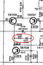
What does this series cap and resistor do in the differential input stage?
Edit: I meant to add: Sometimes I see it in schematics, and some times I don't. Even with the same manufacturer, but different models. Apparently, it isn't absolutely neccessary.
Edit: I meant to add: Sometimes I see it in schematics, and some times I don't. Even with the same manufacturer, but different models. Apparently, it isn't absolutely neccessary.
Attachments
Last edited:
it loads the two halves of the LTP and thus selectively reduces the LTP gain.
Reduced gain is usually used to add phase margin and add gain margin to the amplifier.
Reduced gain is usually used to add phase margin and add gain margin to the amplifier.
Thanks Andrew, although I'm surprised by that answer. (Not doubting you.) I thought that the degeneration resistors did that. That cap/resistor looks more like a high-pass filter.
Thanks Andrew, although I'm surprised by that answer. (Not doubting you.) I thought that the degeneration resistors did that. That cap/resistor looks more like a high-pass filter.
It's kind of both. Andrew is right, it starts to roll off the gain above a certain frequency for stability. That's the purpose. The way it does it is by introducing a freq dependent load, which looks like (and is) a hpf.
jd
Ah . . . thanks for that clarification. So, let me ask this: would it be considered a "mod", or improvement to add this to a circuit that didn't include it already? Was this something omitted as a cost cutting measure?
Ah . . . thanks for that clarification. So, let me ask this: would it be considered a "mod", or improvement to add this to a circuit that didn't include it already? Was this something omitted as a cost cutting measure?
It s not an improvement , it s used because the circuit
is surely instable without it..
If you add this RC circuit to an amp that doesn t need it,
it will undoubtly degrade the performances.
Could I impose on you to expand on that a bit? The reason I ask is because I see it more on higher end units than lower. Its generally located between the differential input pair and a current mirror or CCS. Units that omit it also omit the CM or CCS. If I were to mod a unit, I'd do the full monty, (so to speak), with CM or CCS.
"High end " units are generaly high power, and as such , they
need more gain to reach full power using a standard input voltage
in the vicinity of 1V, so there will be less negative feedback
available to reduce distorsion.
That, with the high output voltage that ask for more gain/bandwith
product, will mandate a higher open loop gain to reach the same
perfs as a say 50Wamp.
More open loop gain is synonym of more instability issues, therefore
these kind of arrangements to reduce the open loop gain at very high
frequencies , where the instabilities occur...
there are many places that compensation can be added.
I suspect they all sound a bit different.
The trick is finding those that are needed and sound right.
I suspect they all sound a bit different.
The trick is finding those that are needed and sound right.
Ok. Thanks again guys. This something I just need to read up on some more. That circuit segment, by the way, is from a Yamaha CA-400. Its a good amp, but not a powerful one.
- Status
- Not open for further replies.
- Home
- Amplifiers
- Solid State
- What does this cap/resistor do in the input stage?