Hi all,
As the title states I've designed and built my dream guitar amp but I'm having a problem. On first power up, I noticed low voltages on my B+. I read ~348Vdc instead of the 438Vdc I should be getting from it. I decided to play through it anyhow and was getting a very faint audio signal under a large and complex low frequency oscillation. The good news is, both sounded very smooth but I decided to go back and fix the obvious problem first before hunting down where the oscillation was coming from.
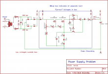
Part of the power supply is shown in the image attached. I've narrowed it down to this little section by disconnecting everything (I even lifted the ground shown in the schematic). Here's the break down:
The supply is fed through a 155-0-155 torroid with the Ct taped and stowed. That 310 Vac is fed to a bridge rectifier, which then feeds a Power scale regulator on it's own PCB, then the standby switch, then back to the main filter cap. The ground end of the filter cap connects the sub-circuit to the main star point via it's own wire.
I get 348V out of the bridge rec, and at the cap...but I get the correct 438 V (310 Vac X 1.414) only on the power scale regulator card between the blocking diodes. No matter what point I choose to take my reference from, the result is the same.
Here's what I've done to isolate the problem:
1. Changed the diodes, and changed them from SiC schottkys to 1N4007's.
2. Isolated this subcircuit by disconnecting wires/components.
3. Lifted the ground so the subcircuit was floating to rule out ground currents.
4. Measured the ground voltages between the bridge rectifier gnd/negative and every ground connection. All low voltages (like .003V).
Did I screw the layout of my PCB up? I drew the schematic attached to show how I grounded it. The one thing I didn't show is the 330k bleeder on the main cap. Other than that this defies my understanding of electronics/physics. Anyone have a clue as to what is going on?
Thank you all for your time!
Brian
As the title states I've designed and built my dream guitar amp but I'm having a problem. On first power up, I noticed low voltages on my B+. I read ~348Vdc instead of the 438Vdc I should be getting from it. I decided to play through it anyhow and was getting a very faint audio signal under a large and complex low frequency oscillation. The good news is, both sounded very smooth but I decided to go back and fix the obvious problem first before hunting down where the oscillation was coming from.
Part of the power supply is shown in the image attached. I've narrowed it down to this little section by disconnecting everything (I even lifted the ground shown in the schematic). Here's the break down:
The supply is fed through a 155-0-155 torroid with the Ct taped and stowed. That 310 Vac is fed to a bridge rectifier, which then feeds a Power scale regulator on it's own PCB, then the standby switch, then back to the main filter cap. The ground end of the filter cap connects the sub-circuit to the main star point via it's own wire.
I get 348V out of the bridge rec, and at the cap...but I get the correct 438 V (310 Vac X 1.414) only on the power scale regulator card between the blocking diodes. No matter what point I choose to take my reference from, the result is the same.
Here's what I've done to isolate the problem:
1. Changed the diodes, and changed them from SiC schottkys to 1N4007's.
2. Isolated this subcircuit by disconnecting wires/components.
3. Lifted the ground so the subcircuit was floating to rule out ground currents.
4. Measured the ground voltages between the bridge rectifier gnd/negative and every ground connection. All low voltages (like .003V).
Did I screw the layout of my PCB up? I drew the schematic attached to show how I grounded it. The one thing I didn't show is the 330k bleeder on the main cap. Other than that this defies my understanding of electronics/physics. Anyone have a clue as to what is going on?
Thank you all for your time!
Brian
Attachments
Just a quick look, but I think you need a Cap connected between your diode bridge and ground. Otherwise, you will get regulator dropout for 80% (wag) of the duty cycle.
Basically this is currently a variation of a choke/resistor input supply, which should be about .9 of the transformer.
Doug
Basically this is currently a variation of a choke/resistor input supply, which should be about .9 of the transformer.
Doug
Don't you need some filter capacitors BEFORE the power scaler, I imagine there some pretty good ripple there as shown. Is that Kevin O'Connor's Power Scaler?
Craig
Craig
Doug...OMG!! I put a 100nF cap in and boom. 438V!!!!!!!!!
Craig, yes it is Kevin O'Connor's Power Scale! Good eyes! I modded it very slightly with the 3 150V zener's to clamp the supply in case of mains overvoltage tries to lift the B+ over the 450V the caps are rated to.
The reason I didn't include any cap prior was that KO'C always showed it this way, of course he never listed voltages though. The idea is to keep DC off the Power Scale pot by using the rectified AC directly, then the voltages can be manipulated and filtered afterward. Come to think of it, he never used a bridge with this circuit, for a circuit like this, would a 2-diode fullwave not behave in this same manner?
I have one of those kits at work, will check the schematic tomorrow. Those kits are usually retrofitted into a already manufactured amp but I don't remember where in the power supply it is supposed to be, before or after the first filter capacitor.
Craig
Craig
Doug and Craig thank you so much for your help. I have every one of KO'C's books and in TUT5 in the Standard chapter, he uses the circuit exactly as I had it except for a 1ohm resistor between the rectifier (2-diode fullwave) and the regulator input blocking diode, then the cap comes after the regulator. Would either of those 2 things cause it not to act as a choke input supply?
You said you used 100nF? I would have thought something like 100uF between the bridge rectifier and the regulator board (+ side of cap to the power supply line - to ground).
Cheers,
Chris
Cheers,
Chris
Doug and Craig thank you so much for your help. I have every one of KO'C's books and in TUT5 in the Standard chapter, he uses the circuit exactly as I had it except for a 1ohm resistor between the rectifier (2-diode fullwave) and the regulator input blocking diode, then the cap comes after the regulator. Would either of those 2 things cause it not to act as a choke input supply?
Not as I understand the circuit. If you have a link, I would be curious to look at the materials.
Doug
- Status
- Not open for further replies.
- Home
- Amplifiers
- Tubes / Valves
- power supply problem in my dream amp...