specs:
input - 3 phase AC magneto (no nutral), voltage output depends on freq , and goes between 0 to 150V
requered output :13-14.7V DC , dead time is not important , but i want it to be a full bridge for higher efficiency .
my idea is to use 6 switches , with some control circuitry that will turn on the right switches when the load voltage is between 13-14.7V
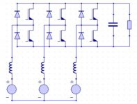
the basic diagram can be seen in pic (which i found googling) , but i dont see the purpose of the 6 diodes , as they turn the circuit into regular full bridge 3 phase rectifier , without any control of the output voltage.
i'm thinking of using power mosfets , and want to know if there are any control ics for this type of circuit.
any help would be apriciated
input - 3 phase AC magneto (no nutral), voltage output depends on freq , and goes between 0 to 150V
requered output :13-14.7V DC , dead time is not important , but i want it to be a full bridge for higher efficiency .
my idea is to use 6 switches , with some control circuitry that will turn on the right switches when the load voltage is between 13-14.7V
the basic diagram can be seen in pic (which i found googling) , but i dont see the purpose of the 6 diodes , as they turn the circuit into regular full bridge 3 phase rectifier , without any control of the output voltage.
i'm thinking of using power mosfets , and want to know if there are any control ics for this type of circuit.
any help would be apriciated
Attachments
Last edited:
3 phase to DC converter
If you buy a dead 3 phase motor drive, the input circuitry will already be in it. Six diode units for rectifying 460 AC to 400V DC (or 200 on 230 3 phase) are a packaged assembly from the manufacturers. Such units also contain boards of valuable 400VDC 3000 uf capacitors in parallel. Many times this part of the circuit is okay. If you use 6 diodes instead of 2, the unit stays powered up if a phase drops out and issues an error code to identify the bad phase. The outputs of these drives get shorted frequently around food factories, where the washdown crew kills them with their hose. Try making the aquaintance of a maintenance man in a factory, to buy his discards, or post an ad on the electronics section of a classified service- $25 or E20 for a dead drive should be about right.
The output waveform and control would be up to you, modern units are microcomputer controlled and the internals are proprietary to the manufacturer typically. Hint- they use thyristors in three triac or six SCR's subassemblies with the heat sink and temperature sensor integrated.
I have one old Wood's drive built before microcomputers, and it has six IC's ST logo 94J535 339. I have no datasheet or control schematic, the drive manual doesn't even discuss which output waveform they are using to approximate, you are on your own. For drive theory the best reference I have found is an obsolete text surplussed by the local community college, "Industrial Electronics Third Edition" by James T. Humphries and Leslie P. Sheets, Delmar Publishers Inc.Albany Ny ISBN 0-8273-3828-7. Enjoy learning!
Last edited:
Use that circuit to convert the AC to about 200v DC, then use a full bridge or forward converter to step it down to the voltage you want.
If you have a high voltage battery on the B+ rails, you can even use the generator as a motor to start the engine and provide additional torque. You can stop the engine at every red light and restart it when needed to save fuel. That's exactly how Honda's IMA system works.
If you have a high voltage battery on the B+ rails, you can even use the generator as a motor to start the engine and provide additional torque. You can stop the engine at every red light and restart it when needed to save fuel. That's exactly how Honda's IMA system works.
Additional salvage opportunities
I might point out the the 6 diode assembly from a motor drive is a "three phase bridge". While is is possible to directly convert the resulting 400 VDC (or 200 from 200 3 phase) to 12 DC by switching, you will save a lot of energy by using a switching converter toroid transformer circuit like a PC switching power supply. In fact, one component of a PC switching power supply is a +-12 VDC convertor. The PC power supply rectifies and upconverts the 120 single phase to feed their output converter toroid transformers and FET's. Your mission, should you chose to accept it, is find a way to replace the input part of a dead PC power supply with this three phase circuit, and repair or reuse the output torroid part that produces the +-12 VDC. You might have to rewind a torroid a little bit. Whole lot easier than starting from scratch. Have fun.
I might point out the the 6 diode assembly from a motor drive is a "three phase bridge". While is is possible to directly convert the resulting 400 VDC (or 200 from 200 3 phase) to 12 DC by switching, you will save a lot of energy by using a switching converter toroid transformer circuit like a PC switching power supply. In fact, one component of a PC switching power supply is a +-12 VDC convertor. The PC power supply rectifies and upconverts the 120 single phase to feed their output converter toroid transformers and FET's. Your mission, should you chose to accept it, is find a way to replace the input part of a dead PC power supply with this three phase circuit, and repair or reuse the output torroid part that produces the +-12 VDC. You might have to rewind a torroid a little bit. Whole lot easier than starting from scratch. Have fun.
Use that circuit to convert the AC to about 200v DC, then use a full bridge or forward converter to step it down to the voltage you want.
If you have a high voltage battery on the B+ rails, you can even use the generator as a motor to start the engine and provide additional torque. You can stop the engine at every red light and restart it when needed to save fuel. That's exactly how Honda's IMA system works.
yes , i want the rectifier to be bidirectional , so i can also turn the magneto with the battery power .of course , some high power step up converter needed.
another question , if i will do that , will the magneto be able to turn with 3 phase square wave signals ? converting the dc to full sine wave 3 phase is much more complicated .
yep , i wont need the 6 diodes , as it will cause the full ac voltage converted to dc on the output.the output cannot be higher then 14.7V , so scrs or mosfets only will be used .I might point out the the 6 diode assembly from a motor drive is a "three phase bridge"
i need the system to be low weight. adding full bridge rectifier + switching + toroid is not such a good idea.Use that circuit to convert the AC to about 200v DC, then use a full bridge or forward converter to step it down to the voltage you want.
Sorry to inform you, but every Mosfet i have ever come accross has a built in body diode to protect the Mosfet itself. The only way round the problem is to incorporate something like a schottky barrier diode in the drain of the Mosfet - that way you'll eliminate any chance of the Mosfet body diode conducting 😉yep , i wont need the 6 diodes , as it will cause the full ac voltage converted to dc on the output.the output cannot be higher then 14.7V , so scrs or mosfets only will be used .
E2A:- What exactly are you trying to do here? Are you attempting to increase the output of a motorcycle alternator? Just asking as it's something i thought about previously & looking at your avatar..... Well, you know 😀
Last edited:
sss,
The circuit you posted is a form of a 3 phase boost converter. You can only increase the output voltage, so 15 volts is impossible. Also, the diodes are needed; they act like free wheeling diodes or catch diodes.
Rick
The circuit you posted is a form of a 3 phase boost converter. You can only increase the output voltage, so 15 volts is impossible. Also, the diodes are needed; they act like free wheeling diodes or catch diodes.
Rick
sss,
The circuit you posted is a form of a 3 phase boost converter. You can only increase the output voltage, so 15 volts is impossible. Also, the diodes are needed; they act like free wheeling diodes or catch diodes.
Rick
its just a pic i found on the net , dont mind it 😛
Sorry to inform you, but every Mosfet i have ever come accross has a built in body diode to protect the Mosfet itself. The only way round the problem is to incorporate something like a schottky barrier diode in the drain of the Mosfet - that way you'll eliminate any chance of the Mosfet body diode conducting 😉
E2A:- What exactly are you trying to do here? Are you attempting to increase the output of a motorcycle alternator? Just asking as it's something i thought about previously & looking at your avatar..... Well, you know 😀
yep , the mosfet diode is a problem .
scrs are problematic also , as it can be turn on , but not off.
so , maybe the best way to go would be GTO thyristor then, 6 of them.
what i'm trying to do :
at first , i'm triying to get rid of the stupid shunt regulator / rectifier , which wastes around 300W of energy 😡
later on , i want to try and use the batery to turn the magneto at certain rpm to increase power - my ghetto KERS system lol.maybe even start the bike by using the magneto , and remove starter completely.
i should write a pantent on this lol.
So i was right then? You are attempting to increase the alternator output? 😀
Not sure what bike you have but my FZR1000 could do with more than 200W of headlights. If you have a permanent magnet 3 phase generator then there isn't a lot you can do (not thought about it). If there happens to be a rotor (regulates from the battery to set the output voltage) & stator (the generator) then there is a way to do it 😉
There is no way you can draw more current from the stator, but you can get it to produce a higher voltage & then step it down to increase the current.
Not easy, possible however 🙂
actually my output power is ok (r1), i just dont like the shunt regulator , which shorts the output to get the right output voltage.
this means , when i drew more power from the magneto (its magneto , not alternator or generator) the regulator heats less and less power is shorted.
this means , when i drew more power from the magneto (its magneto , not alternator or generator) the regulator heats less and less power is shorted.
That's actually a switching regulator.actually my output power is ok (r1), i just dont like the shunt regulator , which shorts the output to get the right output voltage.
this means , when i drew more power from the magneto (its magneto , not alternator or generator) the regulator heats less and less power is shorted.
http://techno-fandom.org/~hobbit/cars/boost-hack/
That's actually a switching regulator.
http://techno-fandom.org/~hobbit/cars/boost-hack/
i know , this is a modern type regulator (not what i got)
is there a problem for ac motors to work properly from square wave signals?
Ah, actually it's a three phase alternator with rotating permanent magnet to generate power in the stator. That's going to be rather a pain in the proverbials to do anything about imo. If they'd used a rotor & sliprings (proper alternator) as with the FZR1000 you'd be laughing 😀
Effectively the rectifier will be a three phase shunt regulator, it could possibly be a series regulator though i doubt it. The problem is no matter what you do you'll have to dissipate power somewhere unless you use some kind of SMPS to convert the overvoltage to increased current output, & if you aren't using that current then you are back to square one 🙄
Effectively the rectifier will be a three phase shunt regulator, it could possibly be a series regulator though i doubt it. The problem is no matter what you do you'll have to dissipate power somewhere unless you use some kind of SMPS to convert the overvoltage to increased current output, & if you aren't using that current then you are back to square one 🙄
- Status
- Not open for further replies.
- Home
- Amplifiers
- Power Supplies
- help with disigning 3 phase AC to DC converter